2. Single-phase 0-20A adjustable current output
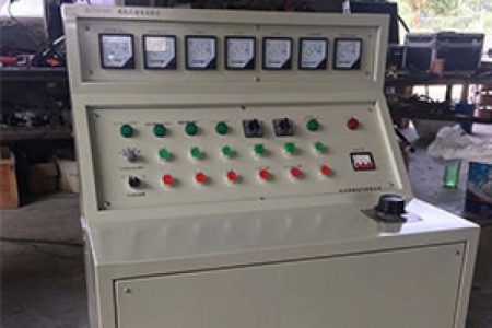
Connect the three-phase four-wire power supply to the power input terminals a, b, c, n on the terminal board of the test bench; according to the test requirements, connect the AC 0-20A output terminals to the switchgear under test. After checking for correctness, close the main power switch. At this time, the corresponding voltmeter for power input indication will show a voltage reading. Switch the power voltage conversion switch to check the voltages between phases a, b, c of the input power. Press the closing button on the left side of the voltage regulator and the closing button for AC 0-20A operation control; turn the voltage regulator handle clockwise while observing the AC 0-20A indicating ammeter until the required current value is reached. After the test is completed, turn the voltage regulator handle counterclockwise to zero voltage and press the corresponding opening button.
3. DC 0-220V adjustable output
Connect the three-phase four-wire power supply to the power input terminals a, b, c, n on the terminal board of the test bench; according to the test requirements, connect the DC 0-220V output terminals to the switchgear under test. After checking for correctness, close the main power switch. At this time, the corresponding voltmeter for power input indication will show a voltage reading. Switch the power voltage conversion switch to check the voltages between phases a, b, c of the input power. Press the closing button on the left side of the voltage regulator and the closing button for DC 0-220V operation control; turn the voltage regulator handle clockwise while observing the DC 0-220V voltage indicating voltmeter until the required voltage value is reached. After the test is completed, turn the voltage regulator handle counterclockwise to zero voltage and press the corresponding opening button.
Note: After the DC test is completed, before removing the wiring, be sure to observe the DC voltmeter to see if its reading is small. If it is greater than 24V, pause briefly to allow the circuit to discharge to a safe voltage before disconnecting.
Explanation: The above three outputs are interlocked with each other, and only one output can be active at a time.
4. DC 0-300V adjustable output
Connect the three-phase four-wire power supply to the power input terminals a, b, c, n on the terminal board of the test bench; according to the test requirements, connect the AC 0-450V output terminals a, b to the switchgear under test. After checking for correctness, close the main power switch. At this time, the corresponding voltmeter for power input indication will show a voltage reading. Switch the power voltage conversion switch to check the voltages between phases a, b, c of the input power. Press the closing button on the left side of the voltage regulator and the closing button for DC 0-300V output control; turn the potentiometer knob clockwise while observing the DC closing power supply 0-300V voltage indicating voltmeter until the required voltage value is reached. After the test is completed, turn the potentiometer knob counterclockwise to zero voltage and press the corresponding opening button.
5. Three-phase AC 100V fixed output
For the high and low voltage switchgear power-on test bench, connect the three-phase four-wire power supply to the power input terminals a, b, c, n on the terminal board of the test bench; according to the test requirements, connect the AC 100V output terminals a, b, c, n to the switchgear under test. After checking for correctness, close the main power switch. At this time, the corresponding voltmeter for power input indication will show a voltage reading. Switch the power voltage conversion switch to check the voltages between phases a, b, c of the input power. Press the closing button on the left side of the voltage regulator and the closing button for three-phase fixed 100V output control; while observing the three-phase 100V fixed output voltmeter, rotate the three-phase 100V voltage conversion switch to observe the line voltages between AB, BC, and CA. After the test is completed, press the corresponding opening button.
6. Press the closing button on the left side of the voltage regulator to obtain fixed AC 220V and DC 220V outputs respectively.
IV. Operating Conditions
1. Ambient temperature: 0~40℃
2. Altitude: <1000m
3. Relative humidity: <85%
4. The workplace should be free of gases, vapors, chemical dust, and other explosive media that seriously affect insulation.
Precautions: 1. When unpacking, check whether the electrical components are damaged or loose.
2. Before use, check that the contacts of each electrical device are in good condition, especially the carbon brush of the voltage regulator.