

Insulating Oil Dielectric Strength Tester Operation Method Step Guide:
1. Insulating oil dielectric strength tester input power supply
Connect the safety ground, plug into the 220V AC power supply, and verify that the power supply is correct.
2. Insulating oil dielectric strength tester oil sample collection
2.1 Adjust the distance between the two electrodes of the oil cup to 2.5mm; turn the feeler gauge rod at one end of the oil cup shaft counterclockwise, adjust the other end electrode to the center position, tighten the screw locking this shaft, place the feeler gauge between the two electrodes and press them tightly, lock the screw, remove the feeler gauge, and screw it clockwise back into the original shaft, as shown in Figure 2.
2.2 Clean the oil cup, place a clean magnetic stirrer inside, fill it with the prepared oil sample, remove the high-voltage cover, place the oil cup between the two high-voltage columns in the high-voltage chamber, place it stably, cover with the high-voltage cover and press the safety switch.
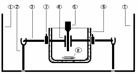
Figure 2 Layout inside the high-voltage chamber
(1) High-voltage chamber (2) High-voltage column
(3) Shaft (4) Electrode
(5) Feeler gauge (6) Oil cup
(7) Shaft fixing screw (8) Magnetic stirrer
3. Preset settings
3.1 The setting value has a total of 6 preset dials as shown in Figure 3:
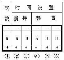
① Indicates the number of tests setting. Press the "+" or "-" sign to select the number of tests you need from 1-9 digits.
②③ Indicate the stirring time setting. ② represents the tens digit, ③ represents the units digit. 1 minute 39 seconds is represented as 99, i.e., 60 seconds + 39 seconds.
④⑤⑥ Indicate the settling time setting. ④ represents the units digit of "minutes", ⑤ represents the tens digit of "seconds", ⑥ represents the units digit of "seconds". 10 minutes 39 seconds is represented as 999, i.e., 9 minutes + 60 seconds + 39 seconds.
4. Function key operation
There are 6 function keys in total, which are momentary keys. Press once to respond to the operation. As shown in Figure 4

4.1 When the insulating oil dielectric strength tester is ready for testing, press the "Measure" key, and the functions of stirring, settling, voltage boosting, and printing will proceed in sequence according to the set values.
4.2 During the voltage boosting process, press the "Stop" key to stop boosting. The value displayed on the digital display is the high voltage value output at the high-voltage terminal at that moment, and it can be kept synchronized and unchanged. Press and hold this key to adjust the high voltage output value down. Pressing the stop key will not change the original running state. As long as you press the "Measure" key again, it will continue to resume operation.
4.3 After the first voltage boost causes the oil sample to break down, the audible alarm will emit a continuous short "beep" for 20 seconds. After the second time, it will emit two short "beeps". After the sixth time, it will emit one long beep and one short beep. After the seventh time, it will emit one long beep and two short beeps. After the average value is displayed, it will emit an uninterrupted "beep" for 20 seconds. If you do not want the audible alarm, press the sound control key once to switch to the light control alarm. The light control indicator will light up, and the number of flashes will be the same as the number of "beep" sounds. Pressing the sound control key again will be ineffective, and the light control will remain unchanged. The sound control will be effective again when the power is turned on again.
4.4 After the insulating oil dielectric strength tester completes the test, if you want to review the data, press the "Display" and "Print" keys. These two keys are repeatable keys. Press the "Display" key once to display one test value, until the average value is displayed, and the repeated display is completed. When pressing the "Print" key, the voltage values will not be printed repeatedly.
4.5 When the "Reset" key is pressed, the display shows the English letters "OCPU", indicating that the reset is in place and in the initial waiting state, referred to as the initial state or OCPU state. If the "Reset" key is pressed during the voltage boosting process, it will not enter the initial state. Similar to the situation when the oil sample breaks down, it will continue to run without changing the original running state. If the "Reset" key is pressed again continuously, it will be confirmed as "Reset" and then enter the initial state.
← Previous
China's First Energy-Saving Conductor Born Next →
Dual-Channel DC Resistance Tester Operation Guide and Precautions
