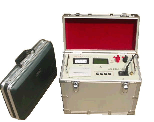
I. Dual-Channel DC Resistance Tester Operation Guide:
1. Connect the AC220V power cord, turn on the power switch, and connect the power supply wires and measurement wires.
2. After the system powers on and enters the initial state, press the "Select/Print" key to choose the desired supply current.
20A | 40A | 50A |
Display 5A indicates supply current selected as 5A 10 A indicates supply current selected as 10A 20A indicates supply current selected as 20A | Display 10 A indicates supply current selected as 10A 20A indicates supply current selected as 20A 40A indicates supply current selected as 40A | Display 10A indicates supply current selected as 10A 20A indicates supply current selected as 20A 50A indicates supply current selected as 50A |
Press the "Select/Print" key to cycle through the options.
When measuring the windings of the same voltage level in the same transformer, select the same current for testing to avoid systematic errors. Generally, the larger the transformer capacity, the smaller the winding resistance, so the test current should be larger. If the range allows, use 10A or 20A for high-voltage winding measurements, and 20A or 40A for low-voltage winding measurements.
3. After pressing the "Confirm" key, the instrument supplies power to the winding and the test process begins.
The "Current Indicator" meter deflects gradually, indicating the selected supply current. The display sequentially shows: "30001": indicating automatic zero calibration; "30002": checking whether charging is complete and entering steady current state; "30003": automatically selecting the measurement range based on the test signal magnitude. After range selection, the measured resistance value is displayed. During the test, if "10000" appears on the display, it indicates the instrument is in under-range state; if "20000" or "30002" remains stationary and the ammeter does not reach the nominal current, it indicates the instrument is in over-range state.
4. If the CH1 indicator light is on, the display shows the resistance value of channel 1 (between V1+ and V1-); if the CH2 indicator light is on, the display shows the resistance value of channel 2 (between V2+ and V2-). During the test, if the "Channel" key is pressed to switch channels, the display shows "H-----", indicating the start of switching. The unit of the displayed value is "mΩ".
5. After the displayed data stabilizes, if printing is needed, press and hold the "Select/Print" key to print the measurement results. In channel 1 state, it prints the resistance value R1 of channel 1; in channel 2 state, it prints the resistance value R2 of channel 2. This key is a scanning key; a single press may not activate the printer, while a long press may print multiple times. Press the key and release it as soon as the printer starts printing to complete a single print. When the printer panel power indicator is off, the printer will not print.
6. For longitudinal testing of on-load tap-changing transformers, a single power supply can complete the test. The instrument program allows, after completing measurement at one tap, to switch to the next tap and then press the "Confirm" key; the display shows "30002" and the instrument proceeds to measure the next tap.
7. For off-load tap-changing transformers, after completing measurement at one tap, press the "Reset" key to put the system in discharge state. The "Current Indicator" meter returns to zero gradually, the "Discharge Indicator" light goes out, and the discharge sound ends, indicating discharge is complete. Only after discharge is complete can the tap switch be changed. An external short-circuit switch can also be connected to speed up the discharge process, then press the "Confirm" key for the next measurement.
8. After testing, press the "Reset" key; the instrument power disconnects from the winding, the "Discharge Indicator" light turns on, the discharge alarm sounds, and the "Current Indicator" meter returns to zero gradually, indicating the winding is in discharge state. At this point, the instrument returns to the initial state and you can continue selecting the desired current. Wait until the "Current Indicator" meter returns to zero, the "Discharge Indicator" light goes out, and the discharge sound ends before rewiring, then press the "Confirm" key for the next measurement.
9. Shutdown: After reset, the instrument is in current selection state, and you can turn off the power. Please turn off the power after the "Current Indicator" meter returns to zero, the "Discharge Indicator" light goes out, and the discharge sound ends, then remove the power supply wires and measurement wires.
10. Printer paper loading:
(1) Turn off the power, remove the printer cover, press the two movable tabs on the sides of the printer inward with your fingers, and pull the printer out from the panel.
(2) Place the paper roll on the paper spindle and push it into the normal position along the spindle slot.
(3) Turn on the power, press the SEL key to turn off the indicator light, then press the LF key; the print head starts moving, feed the paper into the print head inlet until a certain length of paper protrudes.
(4) Insert the printer back into the panel, pull the paper out through the printer cover slot, and replace the cover.
II. Dual-Channel DC Resistance Tester Precautions:
1. If the instrument malfunctions or starts incorrectly, press the "Reset" key to terminate the test process and initialize the system. Upon reset, the LCD displays "00000", and after a few seconds, the current value is displayed.
2. When the instrument is in testing state, do not turn off the power without resetting.
3. Although the instrument has discharge protection circuits, avoid abnormal conditions such as open circuits in the power supply wires or power failure during testing.
4. When testing off-load tap-changing windings, do not change the tap switch until discharge is complete, unless a short-circuit switch is used.