

Usage Method of Bidirectional Substation Area Identification Instrument and Wiring Diagram of Substation Area Identification Instrument
Usage Method of Bidirectional Substation Area Identification Instrument and Wiring Diagram of Substation Area Identification Instrument:
Connection Instructions for Bidirectional Substation Area Identification Instrument:
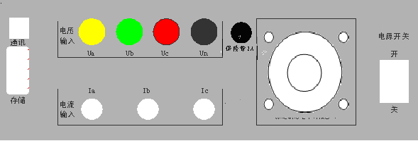
For the bidirectional substation area identification instrument, connect one end of the voltage test leads to the Ua, Ub, Uc, and Un terminals on the rear panel of the instrument according to yellow, green, red, and black respectively. Select the 5A (connected to the secondary side of CT on transformer outgoing lines A, B, C) or 100A (transformer low-voltage neutral line) or 500A (on transformer outgoing lines A, B, C) range clamp-type current transformers; the three clamp meters (A, B, C) with aviation plugs on one end should be connected to Ia, Ib, Ic on the rear panel respectively.
Clamp the clamp meters onto the corresponding phases, and connect the voltage test leads to the circuit under test. The specific wiring method is shown in the figure below:
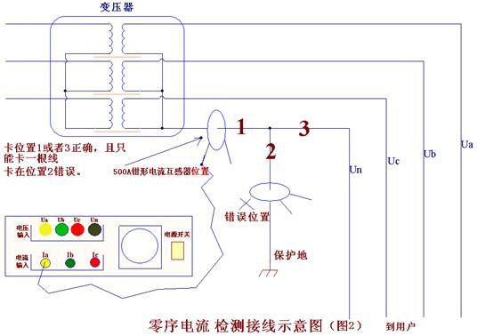
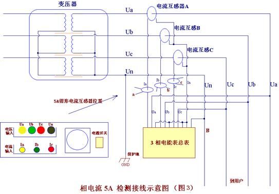
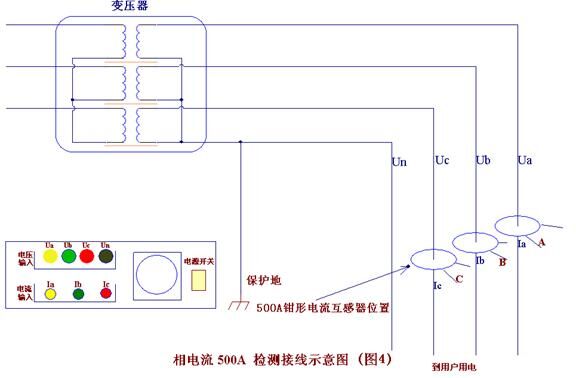
Note: When connecting the voltage test leads, connect the neutral wire first and then the live wire, and the phases must correspond correctly, otherwise the measurement accuracy will be affected.
4.2 Powering On the Bidirectional Substation Area Identification Instrument
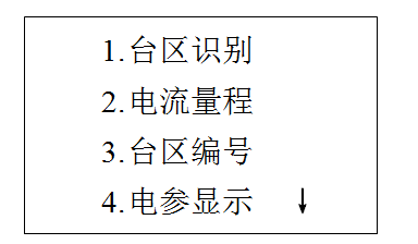
After powering on, enter the main interface (as shown above). The first item is Substation Area Identification. Press key 1 or use the up/down keys to move the cursor to the first item and then press Enter to enter the substation area identification interface. (When pressing keys, do not release your finger until the interface responds.)
Substation Area Identification: Used to set carrier wave on/off and display detected current signals;
Current Range: Used to set current range and test method;
Substation Area Number: Set the number of the current substation area and the number of slave units;
Electrical Parameter Display: Displays voltage and current at the test point;
Polarity Discrimination: Used to check whether the on-site wiring is correct;
(Current detection requires that voltage and current must correspond one-to-one)
Signal Test: Signal test;
Hardware Test: Hardware test.
4.3 Substation Area Identification
Carrier Wave Transmission: Indicates the current status of power line carrier communication. Press the "Start/End" key to switch the carrier wave transmission status. "OK" indicates that power line carrier signals are being transmitted; "NO" indicates that transmission of power line carrier signals is stopped; Current Count: Used to display the number of valid current pulse groups received; Phase: Used to display the phase information of the last valid current pulse signal received. Press the return key to enter the main interface.
4.4 Current Detection
Use the up/down keys to select the current detection type and clamp meter range. Phase Current 5A: Refers to using 3 5A clamp-type current transformers to receive current pulses, connected to the secondary side of the current transformers on phases A, B, and C respectively. The phase clamped by each clamp-type current transformer should correspond to the voltage phase; Phase Current 500A: Refers to using 3 500A clamp-type current transformers to receive current pulses, connected to phases A, B, and C on the transformer outgoing lines. The phase clamped by each clamp-type current transformer should correspond to the voltage phase; Zero-Sequence Current: Refers to using a 100A (or 500A) clamp-type current transformer connected to the transformer neutral line outgoing wire to detect zero-sequence current. In cases where it is inconvenient to connect to the transformer neutral line outgoing wire, a 5A clamp meter can also be used, clamping the clamp-type transformer onto the zero-sequence current line on the CT secondary side. After selecting the current detection type and range, press the return or confirm key to save the settings and exit.
The substation area user identification instrument adopts master and slave unit modes.
The master unit of the bidirectional substation area identification instrument is responsible for sending power line carrier information and detecting current pulse signals. Based on the electrical parameter signals connected to the master unit and the detected current pulse signals, it determines the substation area and phase sequence of the slave unit.
The slave unit is responsible for receiving the power line carrier signals sent by the master unit, sending pulse current as needed, and receiving response information from the master unit. The bidirectional substation area identification instrument displays the information returned by the master unit.
For more details, please refer to:Bidirectional Substation Area Identification Instrument
