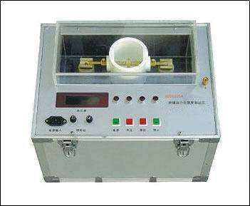
Dielectric Loss Tester Manual and Usage Instructions
Dielectric Loss Tester Manual and Usage Instructions, the following are the operating methods for the GH-6208E dielectric loss tester:
1. Preparation before measurement:
1) Connect one end of the grounding wire to the grounding terminal of the instrument, and the other end to a reliable earth ground, ensuring that the instrument casing is at ground potential.
2) For normal wiring: Insert the high-voltage cable plug into the HV socket on the rear panel, and clamp the red large clamp at the other end onto the high-end lead of the test object. The black small clamp should be left hanging or clamped onto the red large clamp. Insert the CX low-voltage cable into the CX socket, and clamp the red clamp at the other end onto the low-end of the test object, with the black clamp left hanging or connected to the shielding device.
3) For reverse wiring: Insert the high-voltage cable plug into the HV socket on the rear panel, and clamp the red large clamp at the other end onto the high-end lead of the test object. The red small clamp should be left hanging or connected to the shielding device. The Cx socket is not used.
2. Turn on the power switch, the instrument performs self-check. If the self-check is successful, the LCD screen displays the Chinese main menu as shown in Figure 10.
3. Menu selection:
1) Press the key to move the cursor to each menu item, cycling through them. The selected item is displayed in reverse video. The selection key flow is shown in Figure 11.
2) With the cursor on the current item, press the ▼ ▲ keys to change the menu for that item, cycling through options. The flow is shown in Figure 12.
3) After changing the menu to match the test requirements, press the selection key to choose the next item.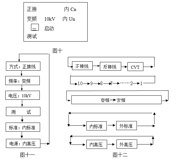
4. Frequency: With the cursor on frequency, press the ↑↓ keys to select fixed frequency or variable frequency:
Cursor on fixed frequency: Press and hold the "Start/Stop" key for more than 1 second to switch to full frequency selection, then press the ↑↓ keys to cycle through 45Hz / 47.5Hz / 50Hz / 52.5Hz / 55Hz / 60Hz / 65Hz.
Power frequency 50Hz measurement: This setting cannot resist interference. Use 50Hz for measurements in the laboratory or for calibration. "45/47.5/55/52.5/60/65Hz": Single frequency measurement, used when studying the change of dielectric loss at different frequencies.
Cursor on variable frequency: Press and hold the "Start/Stop" key for more than 1 second to switch to full frequency selection, then press the ↑↓ keys to cycle through 5-Hz / 6-Hz / 4-Hz":
"5-Hz": Automatic variable frequency at 45/55Hz, suitable for measurement under 50Hz power grid interference.
"6-Hz": Automatic variable frequency at 55/65Hz, suitable for measurement under 60Hz power grid interference.
"4-Hz": Automatic variable frequency at 47.5/52.5Hz, suitable for measurement under 50Hz power grid interference.
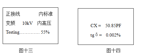
5. Testing: When the cursor is on the "Test" item, press the confirm key for about 3 seconds to start the test. During the test, the display is shown in Figure 13 (normal wiring, variable frequency). When the progress reaches 100%, the test is complete, and then the measurement results are displayed as shown in Figure 14. At this time, the cursor indicates the printer icon; press the confirm key to print the report. The meaning of the measurement results is as follows:
tgδ: The dissipation factor tgδ value of the test object
CX: Measured capacitance value
V: Applied voltage value
I: Current flowing through the test object
F1,F2 : Test frequency
After printing is completed, turn off the power switch. The test is finished.