

New 10A DC Resistance Tester Manual and Usage Guide
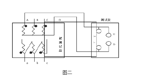
New 10A DC Resistance Tester Manual and Usage Guide, the following is the wiring diagram and operation steps for the GH-6201C DC resistance tester:
A: Single-phase measurement method, see figure below
B. The magnetizing assist method wiring is shown in Figures 3 to 5 (applicable to Y(N)-d-11 connection group).
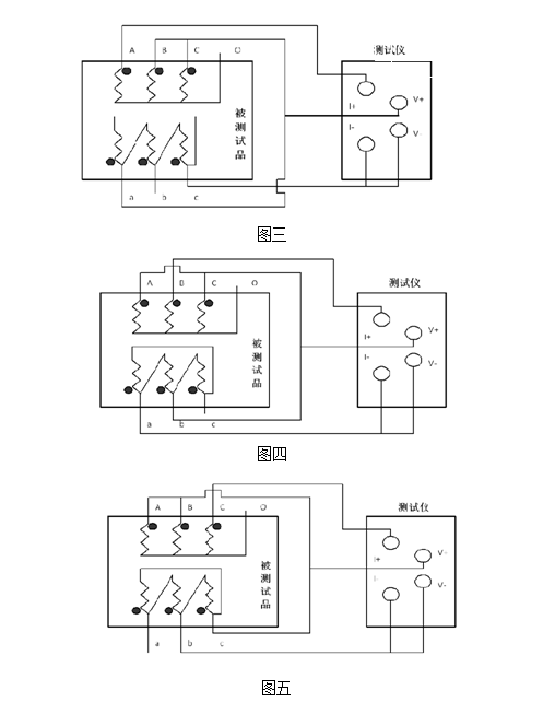
When measuring the low-voltage side of a large-capacity transformer, if the maximum current of the DC resistance tester is relatively small under existing conditions, or to speed up the measurement, the magnetizing assist method can be selected. In the figure above, Figures 3, 4, and 5 are the wiring methods for measuring low-voltage Rac, Rba, and Rcb respectively.
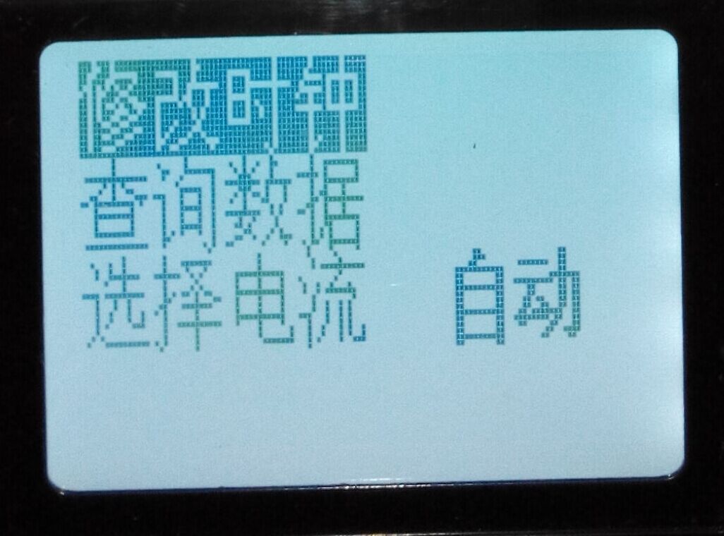
1. The startup page display is as follows:

Press the cycle key to move the cursor among modifying clock, querying data, and selecting current. Press the select key to choose the test current. After selecting the test current, press the confirm key to start measurement. In the above interface, regardless of the cursor position, pressing the confirm key can start measurement.
2. In the above figure, press the cycle key to move the cursor to modify clock, as shown below:
Press the select key to enter the clock modification and query interface, as shown below:
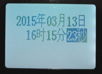
In the above figure, press the cycle key to move the cursor among various date data, press the select key to decrease the data, and press the confirm key to increase the data.
3. On the startup interface, move the cursor to the query data menu, then press the select key to enter the data query interface.
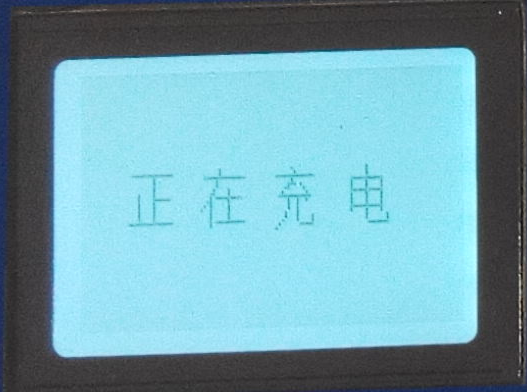
4. After selecting the current, press the confirm key to start testing. The LCD displays "Charging"
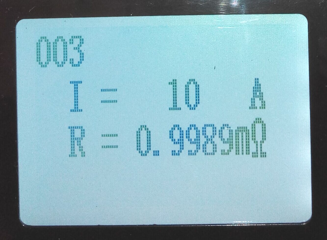
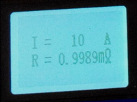
After a few seconds, it displays "Testing", indicating that charging is complete and entering the test state. After a few seconds, the measured resistance value will be displayed, as shown below. When automatic testing is selected, the instrument will automatically select the appropriate output current for testing based on the resistance value of the test object.
5. After completion, press the "Reset" key. The instrument output power is disconnected, and at the same time it discharges, the audible alarm sounds, and the LCD returns to the initial interface state. After the discharge alarm ends, please be sure to wait about 10 seconds before rewiring for the next measurement, or turn off the power and remove the test leads.
VII. Precautions
1. Before measuring the no-load tap changer transformer to switch the tap connection, be sure to press the reset key. After the discharge is completed and the alarm stops, you can switch the tap point.
2. When measuring the high-voltage side resistance of an on-load tap changer transformer, start measuring from 1 to 17 by selecting the automatic gear.
3. Before removing the wires, be sure to wait until the discharge is completed and the alarm stops, then turn off the power before removing the wires.
4. When selecting the current, refer to the range in the technical specifications column, and do not use beyond the range or under the range. When used beyond the range, because the current cannot reach the preset value, even if the test is forced to continue, the result stability is too poor. When under the range, the current is too small, and the data is unstable for large-capacity transformers. When these two states occur, confirm the range and select the appropriate range for testing.
5. If the device suddenly shuts down automatically during the test, it may be due to insufficient battery power. In this case, connect the charger for charging or set the output current below 5A for emergency testing.
This manual corresponds to the new model: DC resistance tester
 Previous: