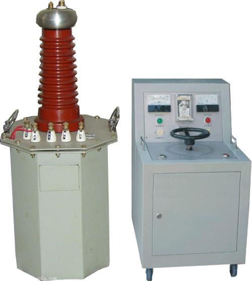
Usage and Precautions of High-Voltage Test Transformer
1. Wiring method for power frequency withstand voltage test using high-voltage test transformer. Before conducting the power frequency withstand voltage test, first select the resistance value of the current-limiting resistor (water resistor) based on the rated capacity of the test transformer, then adjust the sphere gap distance of the discharge ball gap according to the high voltage value to be applied to the test object. To improve the measurement accuracy of the voltage applied to the test object, an FRC resistive-capacitive voltage divider should be connected on the high-voltage side to measure the voltage.
For the power frequency withstand voltage test, after connecting the working circuit, the X terminal (high-voltage tail) of the high-voltage winding of the test transformer, the F terminal of the instrument measurement winding, the shell of the test transformer, and the shell of the power control box (console) must be reliably grounded.
When using three test transformers in cascade for power frequency withstand voltage test, the X terminal of the primary winding, the F terminal of the instrument measurement winding, and the X terminal (high-voltage tail) of the high-voltage winding of the second and third stage test transformers are all connected to the shell of the respective stage test transformer. The main bodies of the second and third stage test transformers must be placed on insulating supports. Except for the first stage, the main bodies of the second and third stage test transformers should not be grounded.
Before connecting the power supply, the voltage regulator of the power control box (console) must be adjusted to the zero position. After connecting the power supply, the green indicator light turns on. Press the start button, and the red indicator light turns on, indicating that the test transformer has been connected to the control power supply and voltage boosting begins.
From the zero position, rotate the voltage regulator handwheel clockwise at a uniform speed to increase the voltage. (The boosting methods include: fast boosting method, i.e., 20S step-by-step boosting method; slow boosting method, i.e., 60S step-by-step boosting method; and extremely slow boosting method for selection.) The voltage starts from zero and increases at the selected boosting speed to 75% of the required rated test voltage, then increases at a speed of 2% of the rated test voltage per second to the required test voltage, while closely observing the indications of the measuring instruments and the condition of the test object. After the specified duration of voltage application to the test object, the voltage regulator should be returned uniformly within a few seconds, and the high voltage should be reduced to below 1/3 of the test voltage. Press the stop button, the high-voltage and low-voltage outputs stop, then cut off the power supply line, and the test is completed.
Precautions during the operation of power frequency withstand voltage test
a. Test personnel should have clear division of responsibilities, set up a safe distance at the test site, carefully check the grounding of the test object and the test transformer, and have a dedicated person to monitor safety and observe the condition of the test object.
b. The main parts of the test object should be cleaned and kept absolutely dry to avoid damage to the test object and errors in test values.
c. For tests on large equipment, generally a no-load boosting test of the test transformer should be conducted first, i.e., boosting to the test voltage without connecting the test object, in order to calibrate the indication accuracy of the instruments and adjust the sphere gap distance of the discharge ball gap.
d. During the withstand voltage test, the boosting speed should not be too fast, and sudden voltage application should be prevented, such as sudden closing when the voltage regulator is not at zero position. Also, sudden power off should be avoided; generally, the switch should be opened after the voltage regulator is reduced to zero position.
e. During the boosting or withstand voltage test, if any abnormal conditions are found, such as (1) large fluctuations in the voltage and current meter pointers, (2) abnormal sounds from the test object, (3) signs of insulation burning or smoking, the voltage should be immediately reduced, the power supply cut off, the test stopped, and the cause investigated.
f. When using this product for high-voltage tests, in addition to being familiar with this manual, the relevant national standards and operating procedures must be strictly implemented. Reference can be made to GB311—83 "Regulations for Preventive Tests of Electrical Equipment" and others.