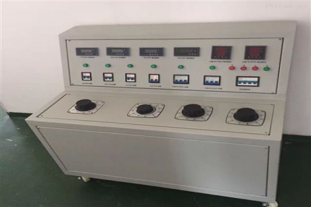
High and Low Voltage Switchgear Power-On Test Device
I. Overview
The GDTS-II high and low voltage switchgear power-on test bench is used by high and low voltage switchgear manufacturers to conduct various power-on tests before factory delivery. It can provide various AC and DC power supplies, facilitating the testing of switchgear and improving work efficiency.
High and Low Voltage Switchgear Power-On Test Bench
II. Technical Parameters:
Input Power: Three-phase four-wire AC 380V
Output Voltage and Current:
1. Three-phase AC 0 – 10A output (<100V, adjustable) one set
2. Three-phase AC 100V output (fixed value) one set
3. AC operating voltage output AC 0~400V, at 220V, current less than 10A
4. DC operating voltage output DC 0~260V
5. DC closing power supply output DC 0~300V (rated current 100A, short-time working current 300A) one set
6. Single-phase AC220V output (fixed value, socket form) two sets,
7. Three-phase AC380V output (fixed value, terminal) one set,
8. Dimensions: 560*520*850mm
9. Weight: 45kg
High and Low Voltage Switchgear Test Bench
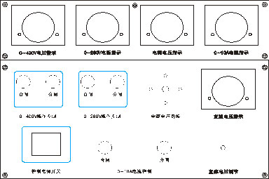
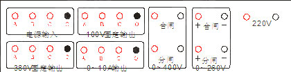
III. Panel Schematic Diagram and Circuit Principle Diagram
Rear Panel
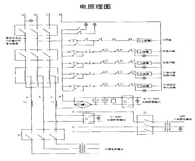
IV. High Voltage Switchgear Power-On Test Bench
Functional Description
1. Before the output terminal, 10A and 16A air switches are connected in series as short-circuit protection. According to user special requirements, items 3-4 in the parameters can be closed and opened simultaneously without interlocking. Please pay attention to the requirements during use; ideally, only one set of power output should work at a time.
2. Items 6-7 in the technical parameters are not controlled by the contactor; as long as the main power switch is closed, single-phase AC220V output (fixed value) and three-phase AC380V output (fixed value) can be output.
3. The DC closing power supply output DC 0-300V (large capacity) is an independent unit that can be used separately from the main cabinet or combined with the main cabinet, directly outputting from the DC 300V output terminal on the rear panel of the cabinet. For detailed instructions, see Section V: HZGK-300A Switch Closing Power Supply.
4. Three-phase transfer switch K1, three-phase AC380V voltmeter,
V. High Voltage Switchgear Power-On Test Bench
Operating Instructions
Taking the inspection of a single-phase AC voltmeter as an example:
1. Connect the input power AC380V
2. Connect the AC operating voltage output power line to the voltmeter
3. Check and confirm the wiring is correct, then turn on the main power switch
4. Return the voltage regulator to zero, and press the "Close" button,
5. Then press the "Close" button for AC operating voltage on the panel
6. Slowly adjust the output adjustment knob to raise the voltage to the required value, and observe the voltmeter.
7. After the test, first press the "Open" button for AC operating voltage on the panel, then press the main "Open" button on the panel. Then, turn off the main power switch.
VI. GK-N Switch Closing Power Supply, external power supply (optional according to user requirements).
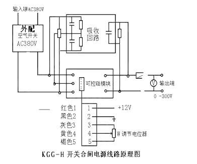
This power supply consists of a fully controlled three-phase rectifier module, phase-shift trigger circuit, automatic adjustment circuit, and absorption circuit.
The transistor intelligent control module integrates the complex automatic adjustment circuit, thyristor, and trigger circuit into one. By adjusting the control signal voltage, the conduction angle of the thyristor is changed, thereby achieving the functions of power regulation and automatic control.
The trigger circuit system, thyristor, and heat-conducting base plate are insulated and isolated from each other, with dielectric strength greater than 2500V, making it safe and convenient to use. The input of the three-phase rectifier module has no phase sequence restriction. It is suitable for resistive and inductive loads.
VII. Instructions for Use:
1. Connect three-phase four-wire AC380V
2. Connect the output DC300V to the load
3. Turn the output adjustment knob counterclockwise to zero.
4. Check and confirm the wiring is correct
5. Close the power switch
6. Slowly adjust the output adjustment knob to raise the voltage to a suitable value.
After the test, first turn the output adjustment knob counterclockwise to zero, then turn off the power switch. After discharge is complete, only then can you start disconnecting the wires.
VIII. Packing List
1. Main unit 1 unit
2. Test leads 2 pieces
3. Manual 1 copy
4. Test report 1 copy
5. Certificate of conformity 1 piece