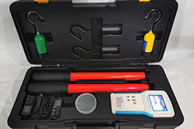
FRD/0.38-220kv High Voltage Voice Wireless Phase Detector
Introduction
The main advantage is that it eliminates the leads connecting the two ends of the power grids (power sources), with a distance of up to 20m, and can pass through walls and partitions (boards), unrestricted by any terrain or facility structure, improving safety.
Operation is convenient, requiring only one operator and one supervisor.
During operation, the instrument sends digital signals to the receiving end through a wireless transmission module, thereby reducing interference, minimizing errors, and greatly improving the instrument's performance.
In use, first operate the receiving device on the conductor of the tested power grid, then operate the receiving device on the conductor of the other tested power grid. If the phases of the two tested power grids are the same, the voice repeatedly prompts: “Phase
same”, if the phases of the two tested power grids are different, the voice repeatedly prompts: “Caution, phase different”.
The insulating operating tube (material) uses the Sanqiu brand moisture-proof insulating tube produced by a military enterprise, which complies with the IEC/1C78 standard and has characteristics such as moisture resistance, high voltage resistance, impact resistance, and bending resistance.
FRD/0.38-220kv High Voltage Voice Wireless Phase Detector
Working Principle and Wiring Diagram
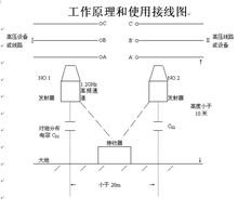
I. Technical Parameters and Component Function Description
1. Technical Parameters
Applicable range: 6~35kV, 110KV, 220KV, 500KV and other voltage levels
Test object status: live parts of lines or equipment
Height above ground: less than 15 meters
Maximum distance between transmitters: less than 30 meters
Equipment operating frequency: 1.2GHZ
2. Transmitter
Transmitter N0.1 and Transmitter N0.2 dimensions: Φ60×120mm, power supply 8.4V (NiMH rechargeable battery)
3. Receiver dimensions: 235×130×43mm
Power battery: 12V NiMH rechargeable battery
.Functions of each component of the receiver
4. Insulating rods: 2 rods, 4 sections in total, use by joining two sections together
Applicable range: 6~35kV, 110KV, 220KV, 500KV and other voltage levels
The insulating rods are made of epoxy resin, each rod is 2 meters long (each rod consists of two sections). The insulating rods are specified to be produced by professional manufacturers, and the length and test voltage comply with the International Electrotechnical Commission IEC60855 and the national standard GB113398-92 "General Technical Conditions for Insulating Rods for Live Working".
Performance Indicators
● Test accuracy: same phase error ≤3o, different phase ≤5o
● Main unit power: 9V ±2V
● Collector power: 7.5V ±1.5V
● Transmission distance between collectors X, Y and main unit: ≤60m
● Type III collector voltage: 0.38kv~500kv
● Operating temperature: –35℃ ~ +50℃
● Insulating telescopic rod: retracted state 650mm, extended state 3000mm
● Packaging box dimensions (length×width×height): 1000mm×140mm×100mm
● Total product weight: 5kg
II. Usage Instructions
1. Self-check
a. Before use, ensure the batteries of Transmitter NO.1, Transmitter NO.2, and the receiver are fully charged. Connect one end of the self-check line to a 220V power supply, and insert the other end into Transmitter NO.1 and Transmitter NO.2, then turn on the transmitter power switch. The transmitter must be placed at least 30cm above the ground, otherwise the receiving sensitivity will be affected.
b. Turn on the receiver power switch, press the test button, the receiver enters a 10-second countdown. After the countdown, it displays the initial waveform of "same phase", and at the same position there are light, text, and sound prompts, indicating that the instrument can be used normally.
2. Field Use
a. Before use, the working requirements of the "Preventive Test Regulations for Electric Power Safety Tools" must be observed.
b. Connect Transmitter NO.1 and Transmitter NO.2 to the insulating rods (the insulating rods must be joined with two sections), turn on the power switch, and the transmitter indicator light shows green.
c. Turn on the receiver power switch, press the test button, the receiver enters a 10-second countdown. After the countdown, contact Transmitter NO.1 and Transmitter NO.2 with the original end and the test end respectively. The transmitter indicator light changes from green to red.
d. When the receiver indicates "same phase", the display is as follows:
1. The waveforms are at the same starting position.
2. The phase angle difference displays "0" or "360".
3. The text indicates "same phase".
4. The same phase indicator light is on (the power indicator light, Transmitter NO.1 and Transmitter NO.2 indicator lights are all on).
5. Sound prompt.
e. When the receiver indicates "different phase", the display is as follows:
1. The starting waveforms are not at the same position.
2. The phase angle difference displays "120" or "240".
3. The text indicates "different phase".
4. The same phase indicator light is not on (the power indicator light, Transmitter NO.1 and Transmitter NO.2 indicator lights are all on).
Precautions
1. On-site operation must comply with the working requirements of the "Preventive Test Regulations for Electric Power Safety Tools".
2. Before use, the instrument must be self-checked, and the batteries of the transmitter and receiver must be fully charged, otherwise the transmission and receiving sensitivity will be affected.
3. During use, do not exceed the effective receiver distance, and place the transmitter in an open area as much as possible.
During use, avoid using radio transmission devices (such as walkie-talkies) simultaneously to prevent interference that may cause the receiver to be unable to distinguish.