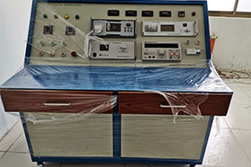
General Inspection
Including appearance inspection; inspection of external dimensions and installation dimensions of electrical apparatus; inspection of clearances and creepage distances; inspection of contact gap, overtravel, and pressure; inspection of operating force of electrical apparatus, etc. The clearance of electrical apparatus refers to the small air insulation distance between different live parts or between two conductive circuits after being disconnected. Creepage distance refers to the leakage distance along the surface of insulating parts that support and fix different live parts or two conductive circuits after being disconnected. When the surface of insulating parts of electrical apparatus absorbs moisture, is heated, or is contaminated, its surface resistance drops sharply. To ensure that insulating parts of electrical apparatus have certain insulation performance, the minimum clearances and surface leakage (creepage) distances are specified in design according to voltage levels and places of use. Contact gap refers to the shortest distance between contacts when the contacts of electrical apparatus are in the open position. Contact overtravel ensures that after certain wear of contacts during operation, the contacts can still close reliably. For manually operated electrical apparatus, the operating force should be inspected to verify whether it meets the requirements for manual operation.
Voltage Drop Measurement
Measure the voltage drop across the tested part after passing a DC current through the contacts or conductive circuit. The purpose of measurement is to evaluate the resistance value across the tested part, and indirectly judge the assembly quality and heating temperature rise of the electrical apparatus by the magnitude of resistance. For example, for contacts of small relays, it is generally not possible to measure the contact temperature with a thermocouple; instead, the method of measuring the voltage drop across the contacts is used for detection.
Temperature Rise Test
Used to verify whether the temperature rise of each component part of the electrical apparatus after energization and heating until stable is within the allowable temperature rise range. The temperature rises of contacts, wires, copper busbar terminals, and coils of different electrical apparatus are specifically specified in standards or technical conditions. If the temperature rise at electrical contacts and conductive copper busbar terminals is too high, it will cause oxidation of the contact surface, and the oxidized contact surface will increase contact resistance, which in turn further increases the temperature rise. If the temperature rise of the coil is too high, the external insulation material will age rapidly, shortening the service life or burning out the coil.
Test and Testing
Insulation Resistance and Withstand Voltage Test
The insulation quality of electrical products is usually evaluated by insulation resistance and withstand voltage tests. Insulation resistance refers to the resistance of the insulation structure between two live parts of an electrical product. Because when a DC voltage is applied between two live parts, there is leakage current in the insulation volume and along the insulation surface, that is, the insulation material has insulation resistance. The insulation resistance of electrical apparatus is related to many factors. When the working temperature of the electrical apparatus rises, the insulation resistance of the insulation material will decrease; when the insulation material is damp, absorbs moisture on the surface, or is contaminated, the insulation resistance will also decrease; after the switching apparatus undergoes the making and breaking capacity test, the insulation structure of the tested apparatus is burned by the arc, and the insulation resistance will also decrease. To ensure the safe use of electrical apparatus, certain requirements are placed on the value of insulation resistance. Generally, the insulation resistance of electrical apparatus should be greater than 1.5 megohms.
The insulation part of electrical apparatus must not only withstand the rated voltage for a long time, but may also withstand overvoltages several times higher than the rated voltage in a short time. Overvoltages are caused by lightning in the atmosphere or switching operations in the line. When the overvoltage exceeds a certain value, surface discharge (called surface flashover) occurs on the insulation material, or insulation breakdown occurs and it becomes a conductive path. The withstand voltage test of low-voltage electrical apparatus is divided into power frequency withstand voltage
test and impulse withstand voltage test.
Rated Making and Breaking Capacity Test
A test to verify that the switching apparatus has the specified making and breaking capacity under specified service conditions. During the test, resistors and reactors are connected to the load side of the switch under test to simulate actual loads (such as motor loads).
Short-circuit Making and Breaking Capacity Test A test to verify the making and breaking capacity of low-voltage electrical apparatus under load short-circuit conditions.
Short-time Withstand Current Capacity Test
A test to verify the ability of low-voltage electrical apparatus to withstand the thermal effect and electrodynamic effect of short-circuit current in the closed state. The electrodynamic force between conductive circuits is proportional to the square of the current passing through the circuit. Therefore, the larger the short-circuit current, the stronger the electrodynamic force. If the mechanical strength of the insulating support parts of the conductive circuit of the electrical apparatus is insufficient, mechanical deformation or even damage may occur. When a large short-circuit current passes in a short time, the temperature of the conductive circuit will rise rapidly, but the temperature rise value should be within the allowable value.
Operating Characteristic Test
Operating characteristics are the main technical performance of low-voltage electrical apparatus. The operating characteristic test includes the measurement of the pick-up and release operating values of the electrical apparatus and the measurement of protection characteristics. For example, for the electromagnetic mechanism of low-voltage electrical apparatus, for the voltage coil, there are certain requirements for the pick-up voltage and release voltage values.
Life Test
The number of operations that low-voltage electrical apparatus can allow is the life of the low-voltage electrical apparatus. For frequently operated electrical apparatus, this is an important technical indicator. For example, for contactors, their life is the main basis for evaluating quality. There are two life indicators for electrical apparatus: one is mechanical life, which refers to the number of no-load operations that the electrical apparatus can withstand without repair or replacement of parts; the other is electrical life, which refers to the number of load operations that the electrical apparatus can withstand without repair or replacement of parts under specified working conditions. The former mainly depends on the robustness of the mechanical structure of the electrical apparatus and the mechanical strength of parts; the latter mainly depends on the wear resistance of contacts. Generally, the electrical wear of contacts is relatively serious, so the electrical life of low-voltage electrical apparatus is only a fraction of the mechanical life.
Immunity Test Some low-voltage electrical apparatus are made of electronic devices, such as AC electronic releases, transistor time relays, etc.
In use, these electronic devices are required to withstand certain external high-frequency and low-frequency interference signals, and their operating values and errors should not exceed the provisions of the product technical conditions. Interference signals in
the range of 0.15~300 MHz are high-frequency, and in the range of 150~15000 Hz are low-frequency. The radiated electromagnetic waves of high-frequency interference signals can act on the tested electrical apparatus from space, or can be added to the tested electrical apparatus from the power supply leads of the tested electrical apparatus. Low-frequency interference signals are mainly added to the tested electrical apparatus from the power supply leads. The immunity test is to simulate high and low frequency interference signals of certain strength, add them to the tested electrical apparatus from space and from the power line, and detect the repeatability error and operating value error of the tested product.