1. Measurement Steps
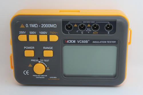
Turn on the power switch "ON/OFF", select the required voltage level. The default voltage is 500V when powered on. Select the desired voltage level, and the corresponding indicator light will illuminate. Lightly press the high voltage "Start/Stop" button, the high voltage indicator light will turn on, and the stable value displayed on the LCD multiplied by 10 is the insulation resistance value of the tested object. When the insulation resistance of the test sample exceeds the upper limit of the meter's range, the first digit of the display shows "1", and the last three digits go out. To turn off the high voltage, simply press the high voltage "Start/Stop" button again. To turn off the entire device, press the power "ON/OFF" button.
Note: During measurement, due to the absorption and polarization process of the test sample, the insulation resistance reading may gradually drift towards larger values or fluctuate slightly, which is normal.
2. Meaning of Terminal Symbols
When measuring insulation resistance, connect the line "L" terminal to the conductive part of the test object that is insulated from ground, connect the ground "E" terminal to the shell or grounded part of the test object, and connect the shield "G" terminal to the protective shield or other non-measured parts of the test object to eliminate errors caused by surface leakage. When measuring the insulation resistance between components of electrical products, you can connect the "L" and "E" terminals to any set of wires. For example, when measuring the inter-phase insulation of a generator, the three groups can be tested in rotation, and the unused phase should be safely grounded.