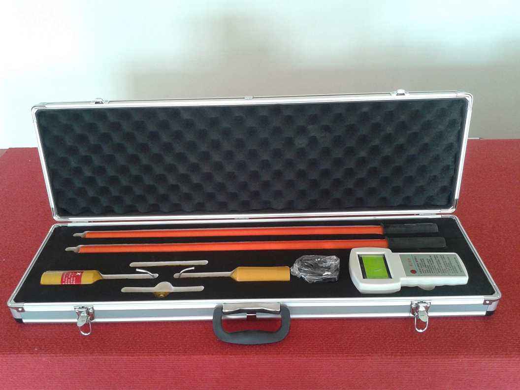
The GH-6603A wireless high-voltage phase checker includes two components that are electrically isolated from each other. The electrodes mounted on the devices can be connected to the tested wires. One orange transmitter has hook-shaped electrodes for hanging onto the wires, while the other yellow receiver has Y-shaped electrodes for easy contact with the wires. These electrodes serve as antennas for transmitting and receiving signals. The ends of both the transmitter and receiver should be connected to insulated operating rods. The transmitter has a dual function and operates in a specific sequence.
A ------------------------------------- -------------------------------------- A’
B ------------------------------------- -------------------------------------- B’
C ------------------------------------ ----------------------------------------C’
The first step is to detect whether the tested wire has voltage. As a voltage detector, it will emit intermittent audible and visual indications for live wires.
The second step: once the voltage detection is completed (after 5-10 seconds), the transmitter automatically switches to phase measurement. The transmitter continuously sends a radio frequency signal with phase characteristics to the receiver. In this case, the line also serves as an antenna, and a continuous light display indicates that the transmitter is working normally in this sequence. The receiver has only one purpose, which is same-phase measurement, while the transmitter is also working to:
1) Ensure that there is voltage on the wire;
2) Receive the radio frequency signal from the transmitter;
3) Compare the measured phase with the received phase characteristic signal in real time;
4) When in phase, the receiver will emit a continuous strong light and sound signal; when out of phase, the receiver emits a weak light signal, which only indicates that the wire contacted by the receiver has voltage.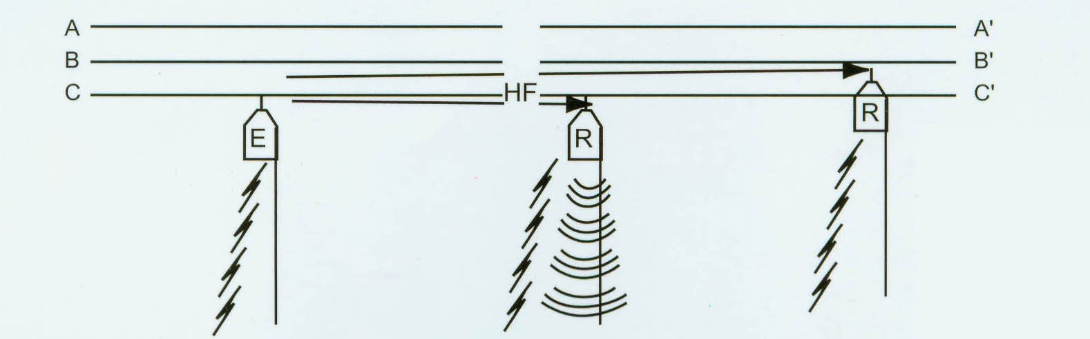
The transmitter and receiver include an integral test system that can test all components: electrical components, batteries, circuits, and antennas. This test is equivalent to an actual contact test on the line. The transmitter and receiver do not have switch buttons; as soon as the instrument contacts a live line, it will automatically start working, and when the measuring electrodes do not contact the wire, it immediately stops working.