2.1. First, check whether the current test lead, voltage test lead, and ground grid lead used for the test have any open circuit (can be measured with a multimeter). Check whether the rust on the ground stakes is completely removed, whether the burial depth is appropriate (>0.5 meters), and simultaneously check whether the connection between the test leads and the ground stakes is conductive. If not, handle and reconnect.
2.2. The length ratio of the current test lead to the voltage test lead is 1:0.618. The length of the current test lead should be 3 to 5 times the diagonal of the ground grid.
2.3. Connect one end of the current test lead and voltage test lead to the instrument according to the specified length, then lay them out in parallel. Connect the other ends to the two ground stakes respectively (as shown in Figure 2).
2.4. Check the laid-out test leads once. Connect one end of the multimeter to the current lead or voltage lead, and the other end to the ground grid lead. If there is no resistance reading, it indicates an open circuit. Confirm it is intact before testing.
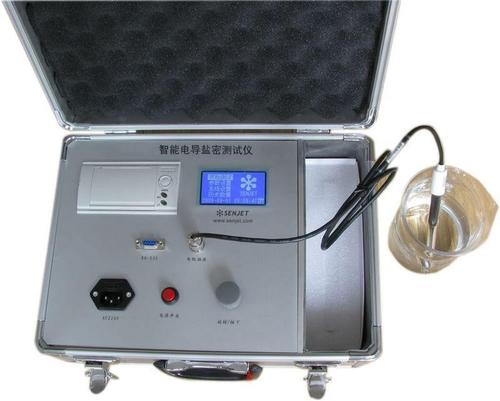
2.5. After confirming the connections are correct, connect the instrument to an AC220V/50HZ power supply and power it on.
2.6. Press the measurement key to start the measurement.
2.7. After the instrument indicates the test is complete, record the test data.
2.8. Turn off the instrument power, disconnect the leads, and the test process is complete.
3. Operating Instructions for the Earth Grid Ground Resistance Tester
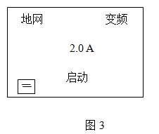
3.1. Turn on the power switch. The computer performs a self-test, and the LCD screen displays the Chinese main menu as shown in Figure 3.
3.2. Press the key to move the cursor to each menu item, with cyclic indication. The selected item is displayed in reverse video. The key selection process is shown in Figure 4.
3.3. With the cursor on the current item, press the ▼ ▲ keys to change that menu item, with cyclic indication. The process is shown in Figure 5.
3.4. After changing the menu to correspond to the test requirements, press the select key to choose the next item.
3.5. Testing with the Earth Grid Ground Resistance Tester: Turn on the high-voltage enable switch. When the cursor is on the test item, press the confirm key for about 5 seconds to start the test. During the test, the screen displays as shown in Figure 6 (Ground Grid, Variable Frequency). When the progress reaches 100%, the test is complete, and the measurement results are displayed as shown in Figure 7. At this time, the cursor indicates the printer icon. Press the confirm key to print the report. The meaning of the measurement results is as follows:
Zx: Measured ground grid impedance value Rx: Measured ground grid resistance value
I: Current flowing through the test object
F1, F2: Test frequencies
After printing, turn off the power switch, and the test is complete.
3.6. During the test, messages such as "Check Power", "Check Current Stake", "Check Voltage Stake", "Check Ground Grid" appearing on the screen indicate the instrument is performing automatic checks. Generally, it takes about 15 seconds. Please wait patiently and do not worry.
4. Detailed Explanation of Test Menu
4.1. Measurement Mode: The instrument can select five measurement modes: "Ground Grid", "Current Stake", "Voltage Stake", "Grounding". The functions of the first three are to measure the ground grid impedance, current stake impedance, and voltage stake impedance, respectively. In general, when conducting tests, you should select "Ground Grid" to measure the impedance of the large ground grid. When the user needs to measure the impedance of the current stake or voltage stake, you can select and measure directly. The "Grounding" mode is used to measure grounding resistance and soil resistivity. The default lead length is 20 meters. The lead length can also be modified.
4.2. Frequency Selection for the Earth Grid Ground Resistance Tester: The instrument can select two measurement frequencies: "Variable Frequency" and "Fixed Frequency". When conducting tests on site, you must select "Variable Frequency" to eliminate electromagnetic field interference at the site. The "Fixed Frequency" mode can only be used for experiments in the laboratory. When the cursor is on "Variable Frequency", press and hold the "Confirm" key for 3 seconds to enter the frequency switching interface. Use the up and down keys to change the measurement frequency. 4-Hz indicates the instrument outputs frequencies of 47.5/52.5Hz during measurement, 5-Hz indicates 45/55Hz, and 6-Hz indicates 55/65Hz. When the cursor is on "Fixed Frequency", press and hold the "Confirm" key for 3 seconds to enter the frequency switching interface. Use the up and down keys to change the measurement frequency among 45, 50, 55, 60, 65Hz single frequencies. "Fixed Frequency" uses a strict 50Hz for measurement. After selecting the appropriate frequency, press the "Confirm" key to exit.
4.3. Current Selection for the Earth Grid Ground Resistance Tester: The instrument provides 5 measurement currents: "1A", "2A", "3A", "4A", "5A". Select the test current based on the impedance of the current stake. In general, a current of 2A is sufficient.
4.4. Auto Print: When the cursor is on the current, press the "Confirm" key once. A small printer symbol will appear or disappear at the bottom left corner of the screen, indicating whether to select or cancel the auto print function. When auto print is selected, the instrument automatically prints the results after the test is complete. When auto print is canceled, if you want to print the results, you need to print manually.
4.5. Manual Print: After the instrument test is complete, the interface shown in Figure 7 appears. Press the key to choose between "Print" and "Exit". If "Print" is selected, press the "Confirm" key once to print the results. If "Exit" is selected, press the "Down" key to store the test results, but you must input the corresponding number (displayed as three digits). Press the "Confirm" key once to return to the initial interface as shown in Figure 3. When the cursor is on "Start", press "Down" to view the stored test results.