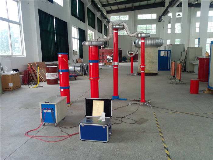
GIS Same-Frequency Same-Phase Withstand Voltage Test System Working Principle, Functional Features, Technical Indicators, Application Scope
1. Application Scope of GIS Same-Frequency Same-Phase Withstand Voltage Test System
GIS equipment is increasingly used in power systems due to its small footprint, high reliability, and low maintenance workload, especially suitable for urban substations. With the increasing number of GIS equipment put into operation in recent years, its advantages are fully demonstrated, but some problems have also emerged during the promotion and adoption of GIS equipment. This is particularly evident in the expansion or maintenance of GIS equipment intervals with double-busbar connections. To meet the conditions for on-site testing and avoid the situation where the test voltage superimposed on the reverse phase voltage of the busbar at the disconnector gap of the busbar causes breakdown and endangers the operation of GIS equipment, the entire busbar at that voltage level must be de-energized, which greatly impacts power supply reliability.
Currently, the main method for on-site AC withstand voltage testing of GIS at home and abroad is the variable frequency resonance method, which changes the frequency of the test voltage to make the withstand voltage test circuit resonate, thereby raising the test voltage to the required value. This method does not require high power supply capacity, is convenient for on-site implementation, and its withstand voltage test effect is similar to that of power frequency testing. However, when testing GIS substations with double busbars, since the frequency of the test voltage differs from the frequency of the operating voltage, the entire station must be de-energized to avoid breakdown at the isolation gap of the withstand voltage circuit, which could damage GIS equipment.
To overcome the problems of the variable frequency resonance method in double-busbar GIS substations, F is set to power frequency 50Hz, and compensation by changing L or C is used to achieve power frequency resonance. Then, frequency and phase are adjusted through the power supply equipment to achieve the test purpose. The GIS on-site AC withstand voltage test method based on same-frequency same-phase technology is adopted, ensuring that the test voltage and operating voltage are of the same frequency and phase.
2. Functional Features of GIS Same-Frequency Same-Phase Withstand Voltage Test System
1) Good test equivalence. The output of this device is a sine wave with low waveform distortion. The waveform distortion rate is <3%, which is different from other types of power supply cabinets (which output square waves and then shape them into sine waves). Therefore, this device does not need to measure the peak value during testing.
2) Fiber-optic control is adopted to completely isolate the high-voltage and low-voltage control circuits.
3) Small size, light weight, flexible handling, very suitable for on-site use.
4) Simple and convenient operation, simple wiring, can improve work efficiency by 50% (compared to generator set method).
5) Safe and reliable, this device integrates multiple protections, including discharge breakdown protection, overvoltage setting protection, output short-circuit protection, startup zero-position protection, bridge arm amplification circuit protection, power curve protection, etc. When any protection is triggered, the device immediately disconnects the test voltage output and cuts off the main circuit power to ensure the safety of test personnel, the test object, and the test system.
6) The signal source in this device is generated by a dedicated chip, controlled by a microcomputer, with high output frequency stability, up to 0.01Hz.
7) The output voltage is controlled by a high-speed microcomputer from abroad, with output voltage instability <1%.
3. Technical Indicators of SP-150 GIS Same-Frequency Same-Phase Withstand Voltage Test System
1) General operating conditions
Altitude: ≤3000m
Ambient temperature: -5℃ to 40℃
Relative humidity: ≤90%
Sunshine intensity: 0.1%W/cm2
Maximum daily temperature difference: <25℃
No conductive dust
No fire or explosion hazard
No corrosive gases to metals and insulation
A reliable grounding point is provided
Placement tilt angle not greater than 5 degrees
Storage location: indoor
Storage environment temperature -20℃ to 40℃, relative humidity ≤90%
2) Performance parameters
Control box
Rated power supply: single-phase AC 220V±10%, 50Hz
Power input: 10W Max
Divider sampling voltage: 0---100V
PT secondary sampling voltage: 0---100V
Operating busbar frequency range: 50.0±0.5Hz
Busbar voltage measurement accuracy: ±(1.5% reading + 1d)
Test voltage measurement accuracy: ±(1.5% reading + 1d)
Phase difference measurement accuracy: ±(1.5% reading + 1d)
Transformation ratio setting range: 1~65535
Power supply cabinet
Rated input voltage: three-phase AC 380V±10%, 50Hz
Single-phase output
Rated output power: 150kW
Output voltage: 0~350V
Rated output current: 0~428.6A
Frequency range: 50.0Hz
Frequency stability: 0.01Hz
Continuous working time under full load: 360 minutes
Output waveform: standard sine wave
Output sine wave distortion rate: ≤1.0%
Output voltage instability: ≤1.0%
Output voltage measurement accuracy: ±(1.5% reading + 1d)
Output current measurement accuracy: ±(1.5% reading + 1d)
Noise level: < 85dB
4. Working Principle of GIS Same-Frequency Same-Phase Withstand Voltage Test System
The high-power output of the power supply device adopts the principle of step-by-step amplification (see figure). From the initial tiny power signal source, after multiple amplifications, high-power output is achieved to meet the test requirements.
The signal source uses a function generator to produce a standard 50.00Hz sine wave signal, which is adjusted by a digital potentiometer for voltage regulation. This process also involves frequency and voltage adjustment during the test. The power supply output frequency is the same as the signal source frequency, and voltage adjustment is implemented in the signal source part. The output of the signal source directly drives the "pre-amplifier" to produce preliminary power output. This "pre-amplifier" output is divided into two paths: one path generates a "synchronous power supply" with the same frequency as the test frequency for partial discharge measurement instruments; the other path drives the "bridge power amplifier circuit" (see figure). The "bridge power amplifier circuit" is the main part for high-power generation, which generates a lot of heat during testing and requires a forced air cooling system for heat dissipation.
In the figure, Q1 to Q4 are four equivalent transistors, corresponding to the four bridge arms of the variable power supply. Each bridge arm is composed of thousands of transistors in parallel, with effective current balancing measures. During the positive half cycle, the pre-amplified signal acts on the bases of Q1 to Q4 through driving transformers (T1 to T4), Q2 and Q3 are cut off, Q1 and Q4 conduct, and current flows from Q1 through the load to Q4, forming the positive half cycle of the sine wave. During the negative half cycle, the analog signal drives the bases of Q2 and Q3, Q1 and Q4 are cut off, Q2 and Q3 conduct, and current flows from Q3 through the load to Q2, forming the negative half cycle of the sine wave, thus forming a complete sine wave across the load.
The "bridge power amplifier circuit" requires a high-power DC power supply as its working power. The power supply of this device is directly taken from a three-phase 380V AC power source, which is sent through a vacuum switch with overcurrent and instantaneous protection to a three-phase bridge rectifier circuit to become pulsating DC, and then through a filter circuit composed of filter inductor and filter capacitor to become smooth DC power for the "bridge power amplifier circuit". Since the capacitance of the filter capacitor reaches tens of thousands of microfarads, direct closing may cause a large charging current that could trip the main power switch. A pre-closing circuit is used to charge the filter capacitor with a small current first, and then close the switch when charged to about 80%, avoiding a large starting inrush current. After opening, the charge stored in the filter capacitor is slowly discharged through a discharge resistor. When using this device, press the "Start" button on the control box, and the fan start, pre-closing, and closing processes are all completed automatically in sequence.
The main circuit of the entire device is controlled by the "fast overcurrent protection" part for the DC working power of the "bridge amplifier circuit". In case of a fault, the working power can be quickly cut off to protect the subsequent circuits.
The output terminals (OUT1, OUT2) of the "bridge power amplifier circuit" are connected to the low-voltage side of the intermediate step-up transformer, and the high-voltage side of the intermediate step-up transformer is connected to the test circuit. The test circuit and the intermediate step-up transformer will not cause an open circuit condition. Due to the large-capacity freewheeling circuit inside the power supply, there is always an energy release channel in the entire test circuit. Therefore, regardless of an internal power supply fault or sudden external power outage, the tested transformer or resonant circuit is not disconnected. This is completely different from traditional test transformers, and there is no overvoltage caused by forced current zero-crossing.