

DC High Voltage Generator Manual and Usage Instructions, the following are the routine operating steps for a DC high voltage generator, for reference only:
1. Preparation before use
(1) Before using the DC generator, check its integrity. The connecting cables should have no open circuits or short circuits, and the equipment should have no cracks or other damage.
(2) Place the control box and the voltage doubling cylinder in a suitable safe position, and connect the power cord, cable, and grounding wire respectively. The protective grounding wire, working grounding wire, and the grounding wire of the discharge rod should all be separately connected to the ground terminal of the test object (i.e., single-point grounding) and ensure good grounding. It is strictly forbidden to connect the grounding wires in series with each other to avoid raising the ground potential and causing a counterattack that could damage the instrument when breakdown occurs.
(3) Check that the power switch is in the off position, and check that the voltage regulator potentiometer is at zero. Set the overvoltage protection dial switch to an appropriate position, generally 1.10 to 1.20 times the test voltage value.
2. No-load voltage rise to verify the overvoltage protection setting
(1) Ensure the power supply is single-phase AC 220V, 50Hz. Turn on the power switch; at this time the green light is on, indicating that the power is connected.
(2) Press the red button, then the red light is on, indicating that the high voltage is connected.
(3) Turn the voltage regulator potentiometer smoothly in a clockwise direction; the output terminal starts to increase voltage from zero. The voltmeter displays the voltage (kV) value on the load test object, while the ammeter displays the sum of the current flowing through the test object and all leakage currents, with the current in microamperes (uA). After reaching the required voltage, record the ammeter reading for the specified time and check the control box and output cable for any abnormal phenomena or sounds.
(4) Reduce the voltage, turn the voltage regulator potentiometer back to zero, then press the green button to cut off the high voltage and turn off the power switch.
3. Conduct leakage and DC withstand voltage tests on the test object
(1) Before conducting the load test, install the high-voltage shielded microammeter on the high-voltage output terminal of the voltage doubling cylinder, and connect the dedicated high-voltage wire to the microammeter and the test object respectively.
(2) Check whether the instrument, discharge rod, voltage doubling cylinder, test object connection wires, and grounding wires are correct, whether the grounding connections are reliable, and whether the high-voltage safety distance meets the requirements before starting the high-voltage test on the test object.
(3) After confirming that the instrument and other items are normal, turn on the single-phase AC 220V power switch; at this time the green light is on, indicating that the power is connected. The DC leakage and DC withstand voltage tests on the test object can begin.
(4) Press the red button, then the red light is on, indicating that the high voltage is connected, waiting to increase the voltage.
(5) Turn the voltage regulator potentiometer smoothly in a clockwise direction; the output terminal starts to increase voltage from zero. The voltage rise speed should be 3-5kV per second for the test voltage. For large capacitance test objects, the voltage rise needs to be slow; otherwise, it may cause voltage overshoot. Also, monitor that the charging current on the ammeter does not exceed the maximum charging current of the DC generator. When the required voltage or current is reached, record the ammeter and voltmeter readings for the specified time.
(6) After the test is completed, reduce the voltage, turn the voltage regulator potentiometer back to zero, then press the green button to cut off the high voltage and turn off the power switch.
(7) After the test is completed, use the discharge rod to discharge the test object multiple times. Only after discharging can you approach the test object and perform wiring work (for detailed discharging, please refer to the discharge rod manual). For small capacitance test objects such as zinc oxide arresters and magnetic blow arresters, slowly adjust the voltage regulator potentiometer to increase the voltage to the required voltage (current) value, then read the voltage (current) value from the digital display. If you need to measure 75% VDC-1mA for zinc oxide arresters, first increase the current to 1000uA and stop at that voltage value (you can record the voltage and current values at this time), then press the yellow button, the voltage will drop to 75% of the original and maintain this state. At this time, you can read the microammeter value and voltage value. After the measurement is completed, turn the voltage regulator potentiometer counterclockwise back to zero, press the green button, and if you need to increase the voltage again, press the red button. For large capacitance test objects, the voltage rise should be even slower, and it is necessary to monitor that the charging current on the ammeter does not exceed the maximum charging current of the generator. Be sure to slow down the voltage rise speed to avoid excessive charging current. After the test is completed, turn the voltage regulator potentiometer counterclockwise back to zero, then press the green button to cut off the high voltage. At this time, do not turn off the power first; the voltmeter still shows a voltage value, which is the stored voltage. Wait until the voltage drops to about 2000V, then use the discharge rod to discharge multiple times to ensure safety.
4. If during use the red light goes out, the green light comes on, and the DC high voltage drops, it indicates that a protection action has occurred. At this time, follow the steps below:
(1) Turn the voltage regulator potentiometer back to zero.
(2) Turn off the power switch; all panel indicator lights are off.
(3) After one minute, wait for the internal low-voltage capacitor to fully discharge before allowing the power switch to be turned on again. Perform a no-load test again, and after investigating the situation, you can increase the voltage again for testing.
5. Note: When conducting cable tests, a current-limiting resistor must be installed. (For other tests, do not use the current-limiting resistor)
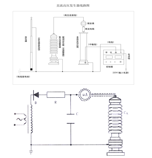
● The indicator lights, switches, knobs, etc. on the control box are clearly marked. When reading this operation manual, please refer to the names of the components on the control box panel.
● On the side of the voltage doubling cylinder chassis, there is a (four) five-pin socket for connecting the control box cable. On the side of the chassis, there is a copper binding post for the grounding terminal to connect the grounding wire.
● The attached high-voltage shielded ammeter is a digital microammeter. The jack on the top of the meter is for connecting the wire to the test object and also serves as the power switch. When not in use, please unplug the plug to automatically turn off the power. When replacing the battery, unscrew the back cover, and after replacement, tighten the back cover.
