

1. Introduction
Oil-paper insulation has been used in medium and high voltage cables for more than 50 years. Due to the large capacitance of these cables, power frequency AC tests have not been performed on site. Moreover, the insulation resistance of oil-paper insulated cables is much lower than that of rubber-plastic cables. DC voltage testing has decades of experience in judging the quality of paper-insulated cables, and practice has proven its effectiveness, providing reliable information on the hazards of defects. Therefore, DC withstand voltage testing has served as the on-site completion acceptance test and periodic preventive test for oil-paper insulated cables, playing a significant role in detecting insulation defects and ensuring the safe operation of the power grid.
With the development of power technology, cross-linked polyethylene (XLPE) power cables are increasingly widely used. In recent years, with the implementation of urban network renovation projects in Shandong Power Grid, high-voltage XLPE cables, especially 110kV XLPE cables, have been widely used in various municipal power supply bureaus. According to the recommended procedures of IEC840 or CIGRE WG21.03, the purpose of on-site testing is not to verify the manufacturing quality of the cable or its accessories, as this has already been confirmed in type tests and routine tests. The purpose of on-site completion acceptance testing is to check whether the cable installation and accessory installation are correct. During transportation, handling, storage, laying, and backfilling, the cable may be accidentally damaged. The inspection method is according to IEC229: for cables with an outer sheath thickness greater than or equal to 2.5mm, apply 10kV DC between the cable shield and ground for 1 minute. For the main insulation withstand test of the cable, IEC recommends two methods:
DC withstand: 3U0 for 15 minutes; AC withstand: U0 for 5 minutes or 1 U0 for 24 hours.
Traditional DC withstand testing has advantages such as light test equipment, good mobility, and low capacity. It works well for oil-paper insulated cables, but for XLPE AC cables, both theory and practice have proven that DC withstand testing is not suitable.
2. Problems with DC Withstand Voltage Testing of XLPE Cables
A general principle of high-voltage testing technology: the test voltage field strength applied to the test object must simulate the operating conditions of high-voltage electrical equipment. The pass/fail conclusion from high-voltage tests should represent whether weak points in the equipment pose a hazard to future operation. This means that the failure mechanism during testing should have the same physical process as that during operation. According to this principle, the problems with DC withstand testing of XLPE cables are mainly manifested in the following aspects:
2.1 Under DC voltage, the electric field distribution in cable insulation depends on the volume resistivity of the material, while under AC voltage, it depends on the dielectric constant of each medium. Especially in cable accessories such as terminal joints and joint boxes, the DC electric field distribution is completely different from the AC electric field distribution, and the aging mechanism under DC voltage is different from that under AC voltage. Therefore, DC withstand testing cannot simulate the operating conditions of XLPE cables.
2.2 XLPE cables have a "memory" effect under DC voltage, storing and accumulating unipolar residual charges. Once the "memory" effect caused by DC withstand testing occurs, it takes a long time to release this DC bias. If the cable is put into operation before the DC residual charge is completely released, the DC bias will be superimposed on the peak of the power frequency voltage, causing the voltage on the cable to far exceed its rated voltage, potentially leading to insulation breakdown.
2.3 During DC withstand testing, electrons are injected into the polymer medium, forming space charges, which reduce the electric field strength at that location, making breakdown difficult. Space charges are prone to form at semiconductor protrusions and contamination points in XLPE cables. However, if a surface flashover occurs at the cable terminal or accessory breakdown during testing, it can cause wave oscillations on the cable core. At locations where space charges have accumulated, the rapid polarity reversal of the oscillating voltage to opposite polarity significantly increases the electric field strength, potentially damaging the insulation and causing multiple breakdowns.
2.4 A fatal weakness of XLPE cables is the ease with which water trees form in the insulation. Once water trees form, they rapidly transform into electrical trees under DC voltage, leading to discharge and accelerating insulation degradation, eventually causing breakdown under power frequency voltage after operation. However, pure water trees can maintain a considerable withstand voltage under AC working voltage and can persist for a period of time.
2.5 Practice has also shown that DC withstand testing cannot effectively detect certain defects under AC voltage, such as mechanical damage to insulation or incorrect placement of stress cones in cable accessories. Locations where insulation is most prone to breakdown under AC voltage often do not break down under DC voltage. Breakdown under DC voltage often occurs at locations where insulation does not normally break down under AC operating conditions.
3. Selection of AC Withstand Voltage Test Methods
Since DC withstand testing cannot simulate the operating field strength state of XLPE cables and cannot achieve the desired inspection effect, it is natural to turn to AC withstand testing to assess the installation quality of cross-linked cables and accessories. The following AC test methods are available:
3.1 Very Low Frequency (0.1Hz) Withstand Voltage Test
Due to the large capacitance of the XLPE cable under test, the capacity of the test transformer required for power frequency testing is also large, making the test equipment bulky and unsuitable for on-site use. Using 0.1Hz as the test power supply theoretically reduces the transformer capacity to 1/500, significantly reducing the weight of the test transformer, making it easier to move to the site for testing. Currently, this method is mainly used for medium and low voltage cable testing, and due to the low voltage level, it cannot be used for high-voltage cables of 110kV and above.
3.2 Oscillating Voltage Test
The oscillating voltage test charges the cable with a DC power supply and then discharges through a discharge sphere gap to a series of resistors and reactors, producing a damped oscillating voltage. This method is more effective than DC withstand testing but still less effective than power frequency testing (1). 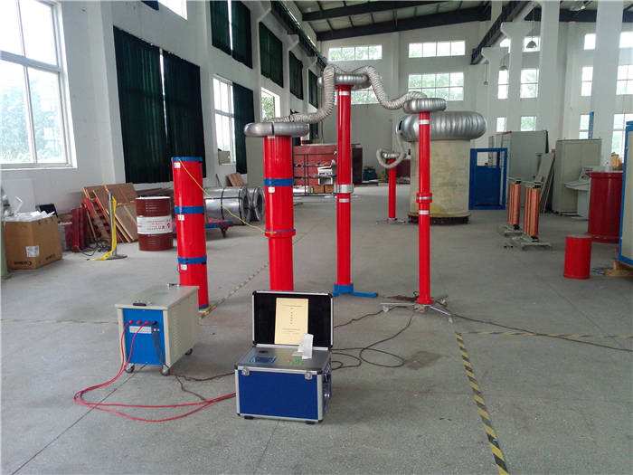
3.3 Resonant Withstand Voltage Test
Adjustable inductance resonant test systems can meet withstand voltage requirements, but due to their heavy weight and poor mobility, they are mainly used in laboratories. Variable frequency resonant test systems not only meet the withstand voltage requirements of high-voltage XLPE cables but also have the advantages of light weight and good mobility, making them suitable for on-site testing. Through extensive investigation and demonstration, Shandong Electric Power Research Institute selected the variable frequency resonant test device developed by Changsha Electric Power Test Development Company. This device uses fixed reactors as resonant reactors and achieves resonance by frequency adjustment, with a frequency adjustment range of 30-300Hz, complying with the recommended AC voltage of power frequency and near power frequency (30-300Hz) in CIGRE WG21.09 "Recommendations for Completion Tests of High Voltage Extruded Insulation Cables". This AC voltage can reproduce the same field strength as under operating conditions and has been proven to be the most effective method.
4. On-site Acceptance Test Examples
After acquiring AC withstand voltage testing capabilities, we began conducting on-site AC withstand voltage acceptance tests on newly installed 110kV XLPE cables in Shandong Power Grid. Below is an example of withstand voltage tests on six 110kV XLPE cables from a certain bureau:
Type: YJLW03
Rated voltage: 64/110kV
Specification: 1×300mm2 copper conductor XLPE insulated power cable,
Manufacturer: Shandong Electric Power Cable & Electrical Appliance Co., Ltd.
Capacitance per unit length: 0.139mF/km, length of a single cable: 1.495km.
Test standard: Apply U0=110kV AC voltage between the cable core and the metal armor layer for 5 minutes.
Since the rated output voltage of the high-voltage side of the intermediate step-up transformer is 15kV, which cannot meet the 110kV test voltage requirement, series reactors are needed for series resonance. Since the test current flowing through the series reactor exceeds its rated current, parallel reactors are added for compensation, effectively forming a series-parallel resonant circuit. The test wiring schematic is shown in Figure 1.
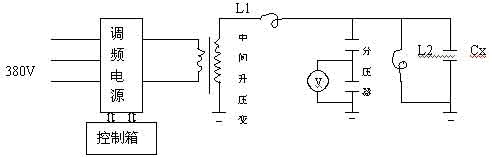
Figure 1 Series-parallel resonant test wiring diagram
In the figure: L1 is one series reactor, L2 is four reactors in parallel, each with an inductance of 200H, rated current of 4A, and rated voltage of 267kV.
In selecting the resonant frequency, we aimed to make the test frequency close to power frequency by changing the number of parallel compensation reactors, while meeting the voltage and current requirements of the test equipment. The following is an estimation of the resonant frequency:
Since the reactance of L1 is much greater than that of the intermediate step-up transformer, or the test voltage is far higher than the output voltage of the intermediate transformer's high-voltage side, the estimation of the resonant frequency can be simplified, equivalent to L1 and L2 in parallel with Cx, hence the following formula:
f=1/2π =55.2Hz
Where: L1=200H, L2=200/4=50H, Cx=0.139×1.495=0.207mF.
During the test, the actual resonant frequency was 55Hz, indicating that the simplified estimation of the resonant frequency is relatively accurate.
The six cables were tested in six separate tests, each with a withstand voltage time of 5 minutes, and all passed.
5. Conclusion
5.1 DC withstand voltage testing cannot simulate the operating conditions of high-voltage cross-linked cables, has poor test effectiveness, and poses certain hazards. It is not recommended to use DC withstand testing for on-site completion acceptance tests.
5.2 AC withstand voltage testing is the most effective means for on-site inspection of the installation quality of cross-linked cables and accessories. The variable frequency resonant device we use complies with relevant IEC and national standards, and through series and parallel connection of reactors, it can meet the on-site AC withstand voltage requirements for 110kV and 220kV high-voltage cross-linked cables.
