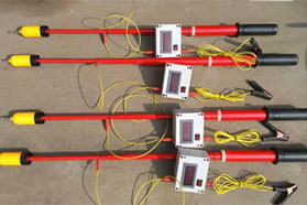
The utility model relates to a new type of telescopic high-altitude wiring clamp.
Background Technology:
The high-altitude test wiring clamp is an essential tool for preventive testing of circuit breakers. In daily preventive testing, the test wires are usually hung directly using a high-altitude wiring clamp with a pole, which is also the most convenient and safe method. However, the wiring clamps currently used by various maintenance teams are assembled from multiple sections of poles. They are relatively feasible for use in 35kV to 110kV circuit breakers, but when it comes to 220kV, especially 500kV circuit breakers, the existing high-altitude wiring clamps are clearly difficult to use. When the existing pole reaches a height of 8-12 meters, the weight of the pole is very heavy and it sways particularly severely. It is difficult for even two people to erect the pole, especially when measuring loop resistance. The existing high-altitude wiring clamps are almost impossible for high-altitude operations at 8 to 12 meters, and the field application effect is poor. The main problem is that the high-altitude wiring clamps currently on the market all use plug-in threaded connection methods, which have poor stability, low working height, time-consuming assembly during use, and inconvenient portability.
Technical Implementation Elements:
The purpose of the utility model is to address some deficiencies in the existing technology and provide a new type of telescopic high-altitude wiring clamp.
To achieve the above purpose, the utility model adopts the following technical solution:
A new type of telescopic high-altitude wiring clamp includes a clamp head and a telescopic insulating clamp pole; the telescopic insulating clamp pole is mainly composed of 5 sections of fiberglass insulating rods nested and installed together in sequence; the clamp head is fixedly installed at the top end of the telescopic insulating clamp pole;
The fiberglass insulating rods are limited between each other using a smart lock structure; the smart lock structure is specifically: at the tail end of the previous fiberglass insulating rod, there is an arc-shaped convex shaft that gradually becomes larger in the clockwise direction. The arc-shaped convex shaft is composed of two inwardly retracted quarter-arc bodies, and each arc body has an unlocking groove and a locking groove at its two ends. The surface of the arc-shaped convex shaft is respectively sleeved with an arc-shaped threaded rubber block; this section of fiberglass insulating rod, together with the arc-shaped convex shaft and the threaded rubber block, is inserted into the interior of the rod body of the next fiberglass insulating rod. Rotate the previous fiberglass insulating rod clockwise or the next fiberglass insulating rod counterclockwise by 45°; due to the friction between the threaded rubber block and the inner wall of the rod body of the next fiberglass insulating rod, the clamping strip rotates from the unlocking groove position to the locking groove to complete locking, and the upper and lower ends of the buckle simultaneously move along the limit groove to the rightmost end of the limit groove to play a limiting role; the threaded rubber block is gradually squeezed and expanded to lock due to moving along the arc-shaped convex shaft that gradually becomes larger counterclockwise, and cooperates with the locking groove for locking; the two threaded rubber blocks form a circle that can generate sufficient friction with the inner wall of the rod body of the next fiberglass insulating rod, enabling it to withstand the pushing and pulling forces during operation; to unlock, simply operate in the reverse direction;
The clamp head is provided with a pulley clamping device; the pulley clamping device includes a slide rail bracket, a fixed pulley, a fixed jaw bracket, a fixed jaw, a guide tube, a spring, a locking mechanism, a pawl bracket, a pawl, a push-pull mechanism, a movable jaw, a movable jaw bracket, a movable pulley, a return mechanism, a slide rail, and a steel wire rope; the fixed jaw is fixed above the slide rail through the fixed jaw bracket; the movable jaw is fixedly connected as one piece with the movable pulley through the movable jaw bracket; the fixed pulley is fixed at the upper end of the slide rail bracket; one end of the steel wire rope is fixed on the fixed jaw bracket, and the other end sequentially winds around the movable pulley and the fixed pulley, and then connects to the locking mechanism of the push-pull rod; the lower end of the slide rail is installed with a return mechanism connected to the movable jaw bracket; by pulling the push-pull mechanism downward to drive the steel wire rope to move, the fixed jaw and the movable jaw slide in opposite directions to clamp, and at the same time, the pawl inserts into the hole teeth of the guide tube to automatically lock the clamping force; conversely, pushing the push-pull mechanism opens the pawl, and the jaws also loosen and return to the original position.
The utility model is further described in that the length of each section of fiberglass insulating rod is 1.7 meters.
The utility model is further described in that the mounting holes of the movable jaw and the fixed jaw are oblique elongated holes.
Usage (installation) process: Before use, first unlock. Hold the upper and lower sections with both hands, and rotate the upper section counterclockwise by 45° to unlock. Each section can be pulled out according to the required length, and can be locked at any position. When locking, rotate clockwise by 45° and hear a click to lock.
Beneficial effects of the utility model:
1. Simple and practical, with reasonable design. The clamp pole adopts fiberglass insulating rods, which greatly reduces the self-weight of the clamp pole while ensuring reliable insulation strength and mechanical strength; the original multi-section assembly method of the clamp pole is changed to a telescopic type, so the volume of the original several rods becomes the volume of one rod; a special strong locking structure is adopted between each section of the rod, which is sufficient to ensure the pushing and pulling force during operation, and each section can be locked at any position.
2. The modified new type of telescopic high-altitude wiring clamp has the characteristics of small occupied volume, light weight, high strength, small sway, and quick assembly, greatly improving work efficiency; it can fully handle high-voltage tests of CT and CVT at 220kV and 500kV voltage levels, as well as loop resistance and dynamic characteristic tests of circuit breakers.
Description of the Drawings
Figure 1 is a structural schematic diagram of an embodiment of the utility model.
Figure 2 is a schematic diagram of the internal structure of the clamp head in an embodiment of the utility model.
Figure 3 is a schematic diagram of the smart lock structure between the clamp poles in an embodiment of the utility model.
Reference numerals:
Reference numerals: 1-slide rail bracket, 2-fixed pulley, 3-fixed jaw bracket, 4-fixed jaw, 5-guide tube, 6-spring, 7-locking mechanism, 8-pawl bracket, 9-pawl, 10-push-pull mechanism, 11-movable jaw, 12-movable jaw bracket, 13-movable pulley, 14-return mechanism, 15-slide rail, 16-steel wire rope, 17-arc-shaped convex shaft, 18-clamping strip, 19-threaded rubber block, 20-buckle, 21-limit groove, 22-rod body, 23-unlocking groove, 24-locking groove.
Specific Implementation Methods
The utility model is further described below with reference to the accompanying drawings and embodiments.
Embodiment 1:
A new type of telescopic high-altitude wiring clamp, as shown in Figure 1, includes a clamp head and a telescopic insulating clamp pole; the telescopic insulating clamp pole is mainly composed of 5 sections of fiberglass insulating rods nested and installed together in sequence; the clamp head is fixedly installed at the top end of the telescopic insulating clamp pole.
As shown in Figure 2, the clamp head is provided with a pulley clamping device; the pulley clamping device includes a slide rail bracket 1, a fixed pulley 2, a fixed jaw bracket 3, a fixed jaw 4, a guide tube 5, a spring 6, a locking mechanism 7, a pawl bracket 8, a pawl 9, a push-pull mechanism 10, a movable jaw 11, a movable jaw bracket 12, a movable pulley 13, a return mechanism 14, a slide rail 15, and a steel wire rope 16; the fixed jaw 4 is fixed above the slide rail 15 through the fixed jaw bracket 3; the movable jaw 11 is fixedly connected as one piece with the movable pulley 13 through the movable jaw bracket 12; the fixed pulley 2 is fixed at the upper end of the slide rail bracket 1; one end of the steel wire rope 16 is fixed on the fixed jaw bracket 3, and the other end sequentially winds around the movable pulley 13 and the fixed pulley 2, and then connects to the locking mechanism 7 of the push-pull rod; the lower end of the slide rail 15 is installed with a return mechanism 14 connected to the movable jaw bracket 12; by pulling the push-pull mechanism 10 downward to drive the steel wire rope 16 to move, the fixed jaw 4 and the movable jaw 11 slide in opposite directions to clamp, and at the same time, the pawl 9 inserts into the hole teeth of the guide tube 5 to automatically lock the clamping force; conversely, pushing the push-pull mechanism 10 opens the pawl 9, and the jaws also loosen and return to the original position.
As shown in Figure 3, the fiberglass insulating rods are limited between each other using a smart lock structure; the smart lock structure is specifically: at the tail end of the previous fiberglass insulating rod, there is an arc-shaped convex shaft 17 that gradually becomes larger in the clockwise direction. The arc-shaped convex shaft 17 is composed of two inwardly retracted quarter-arc bodies, and each arc body has an unlocking groove 23 and a locking groove 24 at its two ends. The surface of the arc-shaped convex shaft 17 is respectively sleeved with an arc-shaped threaded rubber block 19; this section of fiberglass insulating rod, together with the arc-shaped convex shaft 17 and the threaded rubber block 19, is inserted into the interior of the rod body 22 of the next fiberglass insulating rod. Rotate the previous fiberglass insulating rod clockwise or the next fiberglass insulating rod counterclockwise by 45°; due to the friction between the threaded rubber block 19 and the inner wall of the rod body 22 of the next fiberglass insulating rod, the clamping strip 18 rotates from the unlocking groove 23 position to the locking groove 24 to complete locking, and the upper and lower ends of the buckle 20 simultaneously move along the limit groove 21 to the rightmost end of the limit groove 21 to play a limiting role; the threaded rubber block 19 is gradually squeezed and expanded to lock due to moving along the arc-shaped convex shaft that gradually becomes larger counterclockwise, and cooperates with the locking groove 24 for locking; the two threaded rubber blocks 19 form a circle that can generate sufficient friction with the inner wall of the rod body 22 of the next fiberglass insulating rod, enabling it to withstand the pushing and pulling forces during operation; to unlock, simply operate in the reverse direction.
In this embodiment, the length of each section of fiberglass insulating rod is 1.7 meters. The mounting holes of the movable jaw 11 and the fixed jaw 4 are oblique elongated holes.