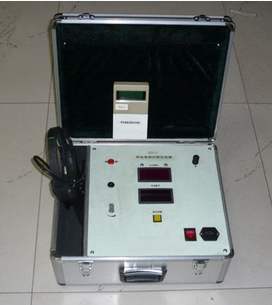
Designed with modern microelectronic technology, it can test faults such as open circuits, low resistance, high resistance, and flashovers in power cables. It features a high degree of intelligence. A large color screen displays with a resolution of 640×480 pixels. It is electrically isolated from the high-voltage circuit, ensuring good safety. High testing accuracy: when the range is less than 1Km, the test error is less than 1m; when the range is greater than 1Km, the test error is less than 4m. It uses a Chinese menu technology, making it easy to master and use. It is equipped with a large-capacity storage card that can save more than 1000 test waveforms, and can be conveniently connected to a computer for file management and remote service functions. It uses a clock marker for easy browsing of waveform files. It uses rechargeable lithium-ion batteries with automatic charging management, dual batteries backing up each other, and continuous working time greater than 4 hours. It is small in size, light in weight, and easy to carry. It is also suitable for distance measurement of long arc faults such as joints and large-area water ingress.
Precautions Before Testing with Underground Cable Fault Tester
1. Preparation before testing
a. Before using the equipment, the shell must be reliably grounded, and the grounding resistance must not exceed 4 ohms.
b. Before testing or use, carefully inspect the inside and outside of the equipment. Keeping the equipment, especially the high-voltage terminals and fast wires, clean is crucial.
c. The maximum working voltage of this equipment can be adjusted and limited to 30KV under capacitive load.
d. Avoid severe vibration when moving the equipment. After moving, the equipment must be left for 1 hour before use.
e. The high-voltage meter scale is calibrated for a capacitive load of 0.01μF.
f. After properly installing the discharge rod, fix its grounding terminal to the box grounding bolt with a screw, and place it on top of the box.
2. Cable fault detection test
a. Use a copper nut to reliably short-circuit the short-circuit plate between the high-voltage terminals on the back of the box.
b. Connect the core wire of the cable to be tested to the high-voltage wiring terminal on the back of the box. Short-circuit the other core wires, shielding wires, and ground wires of the cable and connect them to the terminal. Adjust the discharge sphere gap to 1—2mm.
c. Close the power switch ZK inside the box, turn the transfer switch to the fault detection position, start the control power with the key, press the bell warning button LK to make the bell DL emit a start warning, press the high-voltage box, and press the boost button until the sphere gap discharges.
d. Check along the cable length to determine the damaged location and mark it. If the damaged part is not easily found after discharge, appropriately increase the sphere gap to increase the discharge intensity, making the fault point more clearly exposed.
e. Repeat the above steps until all wounds of each core wire are clearly identified (Note: after each operation, reliably discharge all parts with the discharge rod before proceeding to the next operation).
3. Cable withstand voltage and leakage current test
a. Disconnect the short-circuit plate between the high-voltage output terminals on the back.
b. Connect the core wire of the cable to be tested for withstand voltage to the high-voltage output terminal or, short-circuit the short-circuit plate terminal and other core wires, shielding wires, or ground wires, and connect to the ground terminal.
c. Close the power switch ZK inside the box, start the control power with the key, turn the transfer switch to the withstand voltage test, preset the test time, press the alarm switch to make DL emit a warning, press the high-voltage switch, then press the boost button. After boosting, timing will be automatic.
d. It is qualified if no breakdown or flashover occurs within the specified time.
e. During the withstand voltage test period, the leakage current value of the cable can be read on the microammeter.
f. Switch to other core wires and repeat the above steps until the entire cable is tested.
4. Precautions after use
a. After each test, immediately disconnect QK and use the discharge rod to fully discharge the test piece and all high-voltage parts.
b. Before leaving work every day, cut off the external power main switch (capacity not less than 50A) and turn off the ZK switch inside the machine.