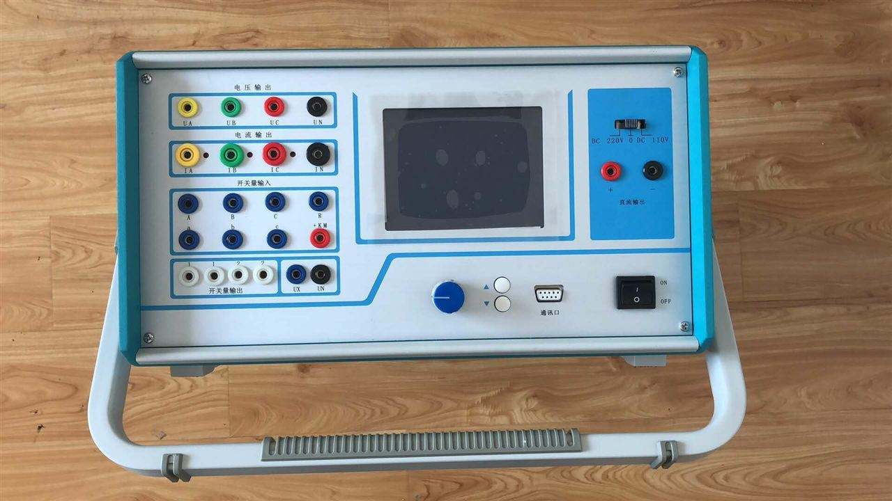
Common Test Methods for Transformer DC Resistance Quick Tester
Generally, the accuracy class of a transformer DC resistance tester should be (0.2 class): for transformers below 120 MVA, the output current should be greater than 10 A; for transformers of 120 MVA and above, the output current should be greater than 20 A; for transformers above 180 MVA, the output current should be greater than 40 A. The output voltage of the instrument should be chosen as high as possible. For a 10A type transformer DC resistance tester, the output voltage should not be lower than 18V, and for a 20A type, it should not be lower than 25V.
The magnitude of the output measurement current determines the measurement accuracy, while the output voltage determines the measurement speed. Therefore, when selecting an instrument, it is essential to clarify the output voltage of the chosen instrument. The instrument should have the function of directly converting the resistance measurement value at room temperature to the resistance value at 20°C, which makes actual measurement more convenient and faster. The QK18 series and QK25 series transformer DC resistance testers have this function.
2. Test Methods:
(1) Use a transformer DC resistance tester for measurement.
(2) Test principle wiring diagram (refer to the test wiring of each DC resistance tester).
3. Test Steps
(1) Measure and record the top oil temperature, ambient temperature, and humidity.
(2) Connect the measuring device or instrument to the winding under test effectively using test leads, and start measurement.
(3) After testing, use the "Discharge" or "Reset" button on the measuring device or instrument to fully discharge the tested winding.
4. Test Result Evaluation Criteria (or Methods)
(1) Convert the measured value to the same temperature using the formula R2 = R1 (T + t2) / (T + t1) (where R1 and R2 are the resistance values at temperatures t1 and t2, respectively; t1 can be taken as the transformer winding temperature during handover test; T is the resistance temperature constant, taken as 235 for copper conductors and 225 for aluminum conductors).
(2) For transformers above 1.6 MVA, the difference among the phase winding resistances should not be greater than 2% of the three-phase average; for windings without a neutral point lead, the line-to-line difference should not be greater than 1% of the three-phase average.
(3) For transformers of 1.6 MVA and above, the phase-to-phase difference generally should not be greater than 4% of the three-phase average; the line-to-line difference generally should not be greater than 2% of the three-phase average.
(4) The resistance of each phase winding compared with previous results at the same location and same temperature should not show significant differences.
(5) The three-phase unbalance rate is an important criterion for judgment, and various standards and regulations have made detailed and clear provisions. When comparing handover and factory tests, the three-phase unbalance rate should not change significantly; otherwise, even if it is less than the specified value, it cannot be simply judged as qualified.
5. Precautions
(1) Measurement should generally be performed after the oil temperature is stable. Only when the oil temperature is stable can it be equivalent to the winding temperature, and the measurement results will not cause temperature conversion errors due to temperature differences.
(2) For large transformers, the charging process during measurement is very long and should be given sufficient attention. Consider using the demagnetization method or magnetization assist method.
(3) Pay attention to fully discharging the tested winding after measurement.