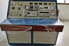
Introduction to Transformer Characteristic Test Bench
Main Functions:
Used to test the DC resistance of switch contacts, circuit breaker contacts, busbars, contacts, SF6 switches, various connections, fuses, and railway connections. Working Principle: The M400 uses a silicon-controlled rectifier circuit to adjust the test current to a preset value. This current, after rectification and filtering, is applied to the sample under test, directly measuring the resistance value. In this current, voltage is applied to the unknown circuit under test and compared with a circuit of known resistance, and the reading is displayed on a digital ammeter. The test principle adopts a four-terminal testing method. The four-terminal connection is used for the unknown resistance under test and its parallel circuit. The test circuit and its selection switch determine the test range.
Technical Specifications:
1. Output Current: 5A, 10A
2. Measurement Range: 5A: 1mΩ~4Ω 10A: 1mΩ~1Ω
3. Resolution: 1μΩ
4. Test Accuracy: 0.2 class
5. Operating Temperature: -10℃~50℃
6. Operating Humidity: 0~80%
7. Power Supply: AC 220V±10% 50Hz±1Hz
Main Technical Indicators:
>Measurement Range: 0~2000Ω. (Six ranges in total)
Test Current: 5A (20mΩ~2Ω); 0.5A (20Ω); 0.05A (200Ω); 0.005A (2000Ω).
>Resolution: 1μΩ (20mΩ range); 10μΩ (200mΩ range); 0.1mΩ (2Ω range); 1mΩ (20Ω range); 10mΩ (200Ω range); 0.1Ω (2000Ω range). >Accuracy: 1mΩ~2000Ω (±0.5%)
>Power Consumption: ≤100W
>Operating Temperature and Humidity: 0℃~40℃; ≤85% RH
>Withstand Voltage: AC 1.5kV 50Hz 1min
>Power Supply: AC220V 50Hz (±10%)
>Dimensions: 350mm(L)×260mm(W)×140mm(D)
>Weight: Approx. 30kg
Safety Measures:
1. Read this manual carefully before using the instrument.
2. The operator of the instrument should have general electrical knowledge.
3. Avoid using the instrument in places exposed to rain, corrosive gases, excessive dust, high temperature, direct sunlight, etc.
4. The instrument should avoid severe vibration.
5. After testing, be sure to wait until the discharge alarm sound stops before turning off the power and removing the test leads.
6. When measuring no-load tap-changing transformers, be sure to wait until the discharge indication alarm sound stops before switching gears.
7. During the test, it is forbidden to move the test clamps and power supply lines.
Precautions:
1. For no-load tap-changing windings, it is not allowed to switch the no-load tap changer during the test or before the discharge is complete.
2. For inductive test objects, it is not allowed to remove the test leads before the discharge is complete (when the buzzer is sounding) to avoid electric shock.
3. If the external AC220V suddenly loses power during the test, the instrument will start automatic discharge. At this time, it is not allowed to remove the test leads immediately; wait 5 minutes before removing them.