Recommended by DARUI Electric
Design Objectives
The design can achieve the following objectives: it can verify the structure of the power grid, draw circuit diagrams, and for three-phase connected lines, it is required to confirm the relative phase of different conductors without any electrical connection between the two measurement components, making the application of the measuring device very flexible and safe.
The device uses radio frequency transmission technology, and its basic working principle is real-time phase comparison. The device can check the presence of rated voltage, and the measured phase angle is considered in-phase within +10° and out-of-phase when greater than +30°.
II. Structural Principle
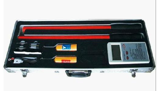
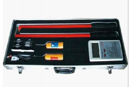
TAG-6000 includes two electrically independent components. The electrodes mounted on the device can be connected to the tested conductor. One orange transmitter has hook-shaped electrodes for hanging onto the conductor, and the other yellow receiver has Y-shaped electrodes for easy contact with the conductor. These electrodes serve as antennas for transmitting and receiving signals. The ends of the transmitter and receiver should be connected to insulating operating rods. The transmitter has a dual function and operates in a certain sequence.
A ------------------------------------- -------------------------------------- A'
B ------------------------------------- -------------------------------------- B'
C ------------------------------------ ----------------------------------------C'
*Step 1: Detect whether the tested conductor has voltage. As a voltage detector, it will emit intermittent audible and visual indications for live conductors.
Step 2: Once the voltage detection is completed, after 5-10 seconds, the transmitter automatically switches to phase measurement mode. The transmitter continuously sends a phase-characteristic radio frequency signal to the receiver. In this case, the line also serves as an antenna. A continuous light display indicates that the transmitter is working normally in this sequence. The receiver has only one purpose, which is phase measurement, while the transmitter is also working to:
1 Ensure there is voltage on the conductor;
2 Receive the radio frequency signal from the transmitter;
3 Compare the measured phase with the received phase-characteristic signal in real time;
4 When in phase, the receiver will emit a continuous strong light and audible signal; when out of phase, the receiver emits a weak light signal, which only indicates that the conductor contacted by the receiver has voltage.
The transmitter and receiver include an integrated test system that can test all components: electrical components, batteries, circuits, and antennas. This test is equivalent to a contact test on an actual circuit. The transmitter and receiver have no switch buttons; as soon as the instrument contacts a live circuit, it will automatically start working, and when the measuring electrodes do not contact the conductor, it immediately stops working.
III. Verification of Radio Frequency Transmission
The frequency generated by the internal module is close to the grid frequency. As long as both instruments are equipped with electrodes acting as antennas, verification can be performed in two ways.
1. Complete Self-Calibration
* Hold one instrument in each hand
* Press the TestButton on the transmitter and wait until it automatically switches to phase measurement mode
* Press the TestButton on the transmitter and simultaneously press the TestButton on the receiver. If the radio transmission is correct, LED2, LED3, and LED4 on the receiver will light up and off regularly, the buzzer will sound synchronously, and LED1 will remain lit.
2. Test with Both Transmitter and Receiver on the Grid
* Hook the transmitter onto a live line; after a few seconds, it will automatically switch to phase measurement mode. Similarly, contact the receiver with another conductor of the same phase, and it should emit audible and visual signals.
* Place the receiver on another phase; it will stop receiving the in-phase signal, no audible signal, only LED1 will be lit.
IV. Measurement Work
Before and after using this instrument, a fully automatic test should be performed on the entire device with electrodes installed. Line voltage measurement uses only the transmitter
* Screw the hook electrode onto the top of the transmitter.
* Attach the transmitter with the electrode to the operating rod.
* Hang the hook on the transmitter onto the tested line. At this time, the operator can see at the bottom of the transmitter: 4 indicator lights: LED1-LED4; a test button: TestButton; a buzzer;
Note: The above information and technical parameters are compiled and released by Yangzhou Darui Electric Co., Ltd.