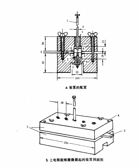
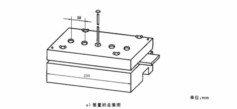
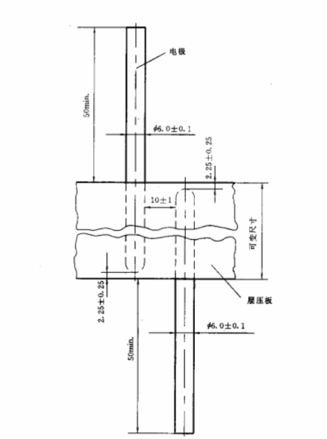
For the material dielectric strength tester, the difference should not exceed 0.1 mm. The cylindrical electrode has a diameter of (6.0±0.1) mm and a hemispherical end. The bottom of each hole is hemispherical to fit the electrode end, ensuring that the gap between the electrode end and the bottom of the hole does not exceed 0.05 mm at any point. Unless otherwise specified in the material specification, the distance between the sides of the two holes along their length should be (10±1) mm, and each hole should extend to within (2.25±0.25) mm of the opposite surface. Two optional forms of ventilated electrodes are shown in Figure 8. When using electrodes with small grooves, these grooves should be positioned exactly opposite to the spacing between the electrodes. In addition to the specimen conditions described above, the following points should generally be noted. When preparing solid material specimens, the two surfaces of the specimen in contact with the electrodes should be parallel and as flat and smooth as possible. For tests perpendicular to the material surface, the specimen must have a sufficiently large area to prevent flashover during the test. For tests perpendicular to the material surface, results from specimens of different thicknesses cannot be directly compared (see Chapter 4). The distance between the two electrodes used to calculate the electrical strength should be one of the following values (according to the specification of the material under test): a) The nominal thickness or the distance between the two electrodes (unless otherwise specified, this value is generally used); b) For tests parallel to the surface, the distance between the two electrodes; c) The thickness measured directly near the breakdown point on each specimen or the distance between the two electrodes. Conditioning before test: The electrical strength of insulating materials varies with temperature and moisture content. If the material under test has specified conditions, these should be followed. Otherwise, unless otherwise agreed, specimens should be conditioned at a temperature of (23±2)°C and a relative humidity of (50±5)% for not less than 24 hours. Surrounding medium: The material should be tested in a surrounding medium chosen to prevent flashover. In most cases, transformer oil conforming to IEC 60296:2003 is a suitable medium. For materials that may swell in mineral oil, other fluids (e.g., silicone oil) may be more appropriate. For specimens with relatively low breakdown voltage, tests can be conducted in air. If tests are to be performed at high temperatures, it should be noted that even at moderate test voltages, discharges at the electrode edges can significantly affect the test values. If it is intended to evaluate the performance of a material in another medium, that medium can be used. The selected medium should have minimal harmful effects on the material under test. The surrounding medium can have a significant impact on the test results, especially for materials that readily absorb moisture, such as paper and paperboard. Therefore, all necessary steps (e.g., drying and impregnation) and the state of the surrounding medium during the test must be determined in the specimen preparation procedure. Sufficient time must be allowed for the specimen and electrodes to reach the required temperature, but some materials may be affected by prolonged exposure to high temperatures. Tests in air at high temperatures: Tests in high-temperature air can be conducted in an oven of any reasonable design, with sufficient volume to accommodate the specimen and electrodes without flashover during the test. The oven should be equipped with air circulation to maintain the temperature around the specimen within ±2°C of the specified temperature and generally uniform. Place a thermometer, thermocouple, or other temperature measuring device as close as possible to the test point to measure the temperature. Tests in liquid media: When tests are to be conducted in an insulating liquid, transformer oil conforming to IEC 60296:2003 should generally be used unless another liquid is more suitable. It must be ensured that the liquid has sufficient electrical strength to avoid flashover. Specimens tested in liquids with a higher relative permittivity than transformer oil may exhibit higher electrical strength than when tested in transformer oil. Impurities that reduce the electrical strength of transformer oil or other liquids may also increase the measured electrical strength of the specimen. Tests at high temperatures can be conducted in a liquid container in an oven (see 7.1) or in a thermostatically controlled oil bath where insulating oil serves as the heat transfer medium. In such cases, appropriate liquid circulation measures should be taken to ensure that the temperature around the specimen is roughly uniform and maintained within ±2°C of the specified temperature. Power supply for electrical equipment: The test voltage is obtained by supplying a variable low-voltage sinusoidal power source to a step-up transformer. The transformer, its power source, and its regulating device should have the following characteristics. With the specimen in the circuit, for all voltages equal to or less than the breakdown voltage of the specimen, the ratio of the peak value to the root mean square (r.m.s.) value of the test voltage should be the square root of 2 (1±5%), i.e., (1.34 to 1.48). The capacity of the power source should be sufficient to meet the requirements of 8.1.1 before breakdown occurs. For most materials, an output current capacity of 40 mA is usually sufficient when using the recommended electrodes. For most tests, the power source capacity range is: 0.5 kVA for tests on small capacitance specimens at 10 kV and below; 5 kVA for test voltages below 100 kV. The variable low-voltage power supply regulating device should allow the test voltage to change smoothly and uniformly without overshoot. When using an autotransformer to apply voltage according to Chapter 10, the incremental increase should not exceed 2% of the expected breakdown voltage.
Material dielectric strength tester report: Unless otherwise specified, the report should include the following:
a) The full name of the material under test, a description of the specimen and its preparation method;
b) The median electrical strength (expressed in kV/mm) or the median breakdown voltage (expressed in kV);
c) The thickness of each specimen (see 5.4);
d) The surrounding medium used during the test and its properties;
e) The electrode system;
f) The method of voltage application and frequency;
g) Individual values of electrical strength (expressed in kV/mm) or individual breakdown voltage values (expressed in kV);
h) Temperature, pressure, and humidity when testing in air or other gases, or the temperature of the surrounding medium when testing in liquid;
i) Conditioning before the test;
j) Description of the breakdown type and location.
If only a simple result report is required, the first six items and the low and high values should be reported.
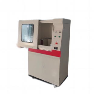
Instrument advantages:
1. *Automatic discharge;
2. *AC voltage, DC voltage, and current test error 1%;
3. *Electrode bracket made of high-quality epoxy board;
4. *Software can continuously perform 10 groups of test comparisons;
5. *Test curves in different colors, can be overlaid for comparison;
6. *Software can set current protection function;
7. *Equipped with host control area, the host can be controlled independently without a computer;
8. *Host has voltage and current display functions;
9. *Built-in exhaust device;
10. *Built-in lighting function;
11. *Discharge alarm device;
12. *Bluetooth remote control;
13. *Three-color light alarm device (green light: door closed properly, yellow light: open door, operate with caution, red light: high voltage present);
14. *Can achieve dual operation via touch screen or computer;
15. *Can achieve combined programming, with separate settings for voltage rise and withstand time in gradient voltage rise;
16. *U-disk download function, allowing test records from the device to be directly downloaded to a U-disk.
Instrument features:
1. Independent control system, modular structure for easy after-sales maintenance, beautiful and elegant appearance, no noise during the entire experiment, automatic electrode alignment and positioning, easy operation, high safety factor, and high precision.
2. Operated and controlled by the device's own touch screen and control panel. If curve analysis is not required, a computer is not necessary.
3. If curve analysis is required, a computer can be equipped, but it only records data and curves and does not control the device, avoiding the need for operators to alternate between the computer and the device, making it more user-friendly.
4. The device has a test parameter memory function. The same test conditions do not need to be set for each test, and the last test parameter settings are remembered even after power off.
5. The test interface is simple and clear, with schematic curve explanations. Different parameters result in different curve trends, making it easy to understand.
6. The control panel is simple, with clear function labels and easy operation.
7. Can record and display up to 10 test records simultaneously, facilitating comparative analysis of test data. Any undesirable set of data can be discarded at any time.
8. Added U-disk download function, allowing test records from the device to be directly downloaded to a U-disk.
9. If equipped with a computer, detailed test reports can be generated, including specific information for each group, comprehensive information for multiple groups, and curves.
10. The device test interface uses both a dashboard and digital display in real-time, making it more convenient to observe the test process.
11. The device has safety warning prompts. The test cannot start if the test chamber door is not closed, and a warning will pop up. A warning will also pop up when the voltage is at full scale (i.e., no output from the high-voltage transformer). If the door is opened during the test, the test will automatically end.
12. Uses Bluetooth data transmission, solving the trouble of passing wires through walls due to isolation barriers and ensuring safe and reliable remote operation;
13. The device is equipped with a three-color alarm. Green light indicates the door is closed properly and the test can start. Yellow light indicates the test chamber door is open, and specimen replacement can be performed. Red light indicates high voltage greater than 0.5KV, and the door should not be opened. After DC test discharge, the alarm light will flash and sound an alarm. (Summary: Green light: door closed properly, yellow light: open door, operate with caution, red light: high voltage present) This standard was drafted in accordance with the rules given in GB/T 1.1-2009.
This standard uses the redrafting method to modify and adopt ISO 6237:2003 "Adhesives - Wood-to-wood adhesive bonds - Determination of shear strength by tensile loading".
Compared with ISO 6237:2003, this standard has some structural adjustments. Appendix C lists a comparison table of clause numbers between this standard and ISO 6237:2003.
The technical differences between this standard and ISO 6237:2003 and their reasons are as follows:
--Regarding normative references, this standard has made adjustments with technical differences to adapt to China's technical conditions. The adjustments are concentrated in Chapter 2 "Normative References", with specific adjustments as follows:
Deleted ISO 291 and ISO 472;
● Added reference to GB/T 2943 (see Chapter 3);
- Added the term "wood failure ratio" (see 3.1);
- Modified the thickness specification in the specimen section, changing the original wood board thickness of 2.5 mm to two types of specimens with two thickness ranges, to increase the practicality of the standard (see 5.2.1 and 5.2.2);
- Added the calculation formula for wood failure ratio for ease of operation (see 9.4);
- Added domestic wood species suitable for adhesive shear testing in Appendix B for ease of use (see Table B.2 in Appendix B).
This standard has made the following editorial modifications:
- Changed the standard name to "Test method for tensile shear strength of wood adhesives".
This standard was proposed by the China Petroleum and Chemical Industry Federation.
This standard is under the jurisdiction of the National Adhesive Standardization Technical Committee (SAC/TC 185).
Drafting units of this standard: Jiangsu Black Pine Forest Adhesive Factory Co., Ltd., Wood Industry Research Institute of Chinese Academy of Forestry, Gelianghao New Materials Co., Ltd., Shanghai Donghe Adhesive Co., Ltd., Zhongke Huayu (Fujian) Technology Development Co., Ltd., Shanghai Rubber Products Research Institute Co., Ltd.
Main drafters of this standard: Ren Yiping, Liu Pengkai, Zhang Jianqing, Lu Yunjie, Yang Meng, Yin Ping, Lu Linsen, Yan Caibin, Gao Yanxiang, Zhu Jianlan.
GB1408-2016 GB/T 507-2002
GB/T1695-2005 DL429.9-91
GB/T3333 Determination of breakdown voltage of insulating oil
HG/T 3330 Determination of dielectric strength of insulating oil
GB12656 ASTM D149.
Main functions:
1. During the test, the test curve can be dynamically drawn, and the curves can be overlaid in multiple colors for comparison.
2. Test data can be edited and modified for flexible application;
3. Test conditions and test results can be automatically stored;
4. The test report format is flexible and variable, suitable for different user needs;
5. The validity of curve data in a group of tests can be manually selected;
6. Test result data can be imported into Excel and Word documents for editing;
7. The overcurrent protection device has sufficient sensitivity to cut off the power within 0.1S when the specimen breaks down;
8. Durability of instrument operation: The instrument can be operated continuously without the need to stop periodically to protect the instrument.
9. The software can set administrator and individual user parameters and report storage permissions. Test method for tensile shear strength of wood adhesives
1 Scope
This standard provides a method for determining the shear strength of wood adhesives by tensile loading using standard specimens under given environmental conditions.
This standard applies to the determination of tensile shear strength of adhesives when wood is bonded parallel or perpendicular to the grain.
Normative references: The following documents are indispensable for the application of this document. For dated references, only the dated version applies to this document. For undated references, the latest version (including all amendments) applies to this document.
GB/T 2943 Adhesives - Terminology
3 Terms and definitions
For the purposes of this document, the terms and definitions given in GB/T 2943 and the following apply.
3.1
Wood failure ratio: The percentage of the area of wood failure on the bonding surface to the bonding area when the bonded specimen fails.
4 Test equipment
4.1 Specimen preparation equipment
4.1.1 Balance: used to weigh the mass when mixing adhesives in proportion, with an error range of 1%.
4.1.2 Mixing equipment: with low oxygen increase and capable of uniformly mixing adhesive components (except foam adhesives).
4.1.3 Adhesive application equipment: such as wire-wound rods, roller coaters, curtain coaters, or suitable manual applicators. It should be able to apply the adhesive uniformly within a deviation of 5%.
4.1.4 Bonding equipment: equipment that can provide pressure as required during the bonding process with a deviation within 5%, such as platens, clamps. If hot pressing is required, the hot platen should maintain the temperature within 2°C during the hot pressing process. · Cut to the adhesive layer but not beyond it.
The width of the saw blade.
· The grain direction of the two faces of the specimen.
Adhesive layer
· The grain direction of the surface veneer (the core veneer should be perpendicular to the grain of the surface board).
Figure 1 Specimen configuration
5.2.1 Use boards with a thickness of 2.5 mm to 5.0 mm to make 2-layer structure specimens
Process the wood board into strips of 260 mm × 25 mm, bond them with wood adhesive, and then process the specimen according to Figure 1a). The grain of both board surfaces should be parallel to the long side of the specimen.
The specimen is mainly used for bonding structural wood or glued laminated timber.
5.2.2 Use boards with a thickness of 1.5 mm to 2.5 mm to make 3-layer structure specimens
For 3-layer or cross-bonded structures, see Figure 1b). The grain of the surface boards should be parallel to the long side of the specimen, and the middle layer should be parallel to the short side of the specimen, i.e., its grain is perpendicular to the grain of the outer two layers. Specimens for 3-layer or cross-bonded structures should be sampled according to the arrangement in Figure 2.
The specimen is mainly used for bonding wood-based panels (thin veneers, plywood, or particleboard).
Note: Both types of specimens can be used to test the strength of adhesives for wood joints, but the values obtained from the two types cannot be compared. The 2-layer specimen is used for wood-based substrates with parallel grain, while the 3-layer specimen is mainly used for wood-based panels such as plywood or particleboard. 5.3
Adhesive application
5.3.1 Prepare the adhesive according to the instructions of the adhesive manufacturer.
5.3.2 Apply the adhesive according to the specifications provided by the adhesive manufacturer (whether the bonding surface is sanded or not is agreed upon by the parties in advance):
Process the base board with a thickness of 2.5 mm to 5.0 mm into strips of 260 mm × 25 mm, bond them in pairs along the grain, allow to stand for the specified time (provided by the adhesive manufacturer), and then lap them into a 2-layer structure specimen according to Figure 1a);
For base boards with a thickness of 1.5 mm to 2.5 mm, cut them to appropriate sizes according to Figure 2, apply adhesive, allow to stand for the specified time, then assemble three pieces into a 3-layer structure plywood according to Figure 1b), cure, and cut into specimens. GB/T 33333-2016
Other methods that can saw out ideal specimens can be used for cutting. Mark the specimens as shown in Figures 1 and 2. When marking the notches, the base board should be completely cut through to the glue line.
7.2 The arrangement of 3-layer specimens to be tested is carried out according to Figure 2. Note that the edges of the base board should be removed before cutting to avoid affecting the tensile shear strength of the specimens. Mark the notches to the second glue line. After marking the base board, saw each specimen to be tested from the base board. Number each specimen in sequence and indicate the different base boards. When conducting related tests, ensure consistency in sampling from each base board.
7.3 Store the specimens to be tested under the environmental conditions described in Chapter 6 until testing. However, this does not apply when cutting the specimens.
8 Test procedure
8.1 Clamp both ends of the specimen to be tested (hereinafter referred to as the specimen) in a pair of movable grips in the tensile testing machine (4.2.3) so that they are in a straight line. The center of the specimen should pass through the axis of the movable grips of the testing machine, so that the notch of the specimen is exactly 5 mm from the bottom edge of the grips. Place the specimens from each board alternately into the mechanical test grips in numerical order, and place the tested and untested specimens on the left and right sides of the machine, respectively. The test should be completed within (60±20) seconds.
8.2 Record the maximum load and wood failure ratio at failure for each specimen. The data estimation is as described in 8.3. The failure load accuracy is 10 N.
8.3 Procedure for determining wood failure ratio: Illuminate the specimen with an inclined light source. The light source (a clean 150 W incandescent bulb and a 15 W fluorescent tube as light 9 Test results
9.1 The test results are expressed as the maximum failure load (in N) and shear strength (in MPa) for each specimen.
9.2 The shear strength of the specimen is calculated according to formula (1), accurate to 0.01 MPa:
=x1
_Pmax
-.…-……………**(1)
Where:
Work - tensile shear strength of the specimen, in megapascals (MPa);
pu-- failure load of the specimen, in newtons (N);
b - width of the bonding surface of the specimen,