This section provides recommendations for using this DC regulated power supply with modular switching power supplies.
Since the modular switching power supply does not have a large-capacity electrolytic capacitor at its input front stage, it will cause significant interference to the input front stage during operation. Therefore, it is recommended to add an electrolytic capacitor at the input front stage of the modular switching power supply. The selection principle for the electrolytic capacitor is: the rated voltage should be greater than 1.2 times the maximum supply voltage of the module power supply; the capacitance can be selected based on the current flowing through the DC bus across the capacitor, and can be quickly selected according to the ratio of 1A1000uF. The following wiring method is recommended:
Figure 2-6 Connection diagram for a single modular switching power supply
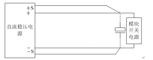
Figure 2-7 Connection diagram for multiple modular switching power supplies
>
Figure 2-1 AN50405 Front Panel Diagram
Front Panel Description:
1. Power switch: Connects or disconnects the input power of the device.
2. START button: Starts the output.
3. STOP button: Stops the output or exits the alarm state.
4. LCD display
5. CONTRAST adjustment knob: Adjusts the LCD display contrast.
6. FINE knob: Modifies the preset voltage value (step 0.01V) or preset current value (step 0.1A).
7. COARSE knob: Modifies the preset voltage value (step 1V) or preset current value (step 10A).
8. CV indicator light: When this light is on, it indicates the device is operating in constant voltage output mode; when off, it indicates the device is operating in current limit output mode.
9. Alarm indicator light: When this light is on, it indicates the device is in a fault state.
10. Power indicator light: When this light is on, it indicates the power input is normal.
11. MENU key: System parameter settings.
12. SET key: Selects the parameter to be set.
13. 28.5V shortcut key: Sets the output voltage to 28.5V.
14. STORE key: Modifies the number of stored groups.
15. UP (increase): Increases the preset voltage value (step 0.1V) or preset current value (step 1A).
16. DOWN (decrease): Decreases the preset voltage value (step 0.1V) or preset current value (step 1A).
17. RECALL key: Recalls the memory group (M01-M10), this key is only valid in standby mode.
18. ENTER key: Press this key to save the preset data and return to the standby interface.
19. EXIT key: Press this key to discard the preset data and return to the standby interface.