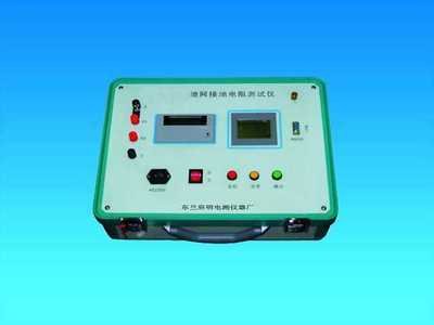
LargeGround Grid Grounding Resistance TesterTest Operation Steps
1) First, check whether the current wire, voltage wire, and ground grid wire used for the test have any open circuit (measure with a multimeter), whether the rust on the ground stakes is cleaned, and whether the burial depth is appropriate (>0.5 meters). Also check whether the test wire and ground stake are connected properly. If not, handle and reconnect.
2) The length ratio of the current test wire to the voltage test wire is 1:0.618. The length of the current test wire should be 3-5 times the diagonal of the ground grid.
3) Connect one end of the current test wire and voltage test wire to the instrument according to the specified length, then lay them out in parallel. Connect the other ends to two ground stakes respectively.
4) Check the laid test wires once. Connect one end of the multimeter to the current wire or voltage wire, and the other end to the ground grid wire. If there is no resistance reading, it indicates an open circuit. Confirm it is intact before testing.
5) After confirming the connections are correct, connect the instrument to AC220V/50HZ power and power it on.
6) Press the measurement key to start measurement (during the test, the LCD displays "Testing, please wait...").
7) After the instrument indicates the test is complete, record the test data (this instrument can repeat measurements multiple times).
8) Turn off the instrument power, remove the connections, and the test process ends.
Self-Diagnosis Instructions During Testing
1) If the instrument displays "Loop resistance too high", it indicates poor contact between the "current wire" connection and the "current electrode" ground stake, or too few ground stakes. Add more ground stakes to reduce loop resistance. The depth of ground stakes should be no less than 0.5m.
2) "Voltage electrode wiring error" means poor contact of the voltage wire or it is not connected.
3) If the instrument displays "Over range", it means the measured ground grid resistance is greater than 40Ω.
4) If the instrument displays "Ground electrode current electrode wiring error", it means the "current wire" or "ground wire" is not connected.
5) If the measured value displayed by the instrument is extremely low (<0.01Ω), it may be that the voltage wire is not connected.