

1 The Importance of Grounding Devices in Power Grids
(1) The main function of grounding is to prevent electric shock to personnel, damage to equipment and lines, prevent fires, prevent lightning strikes, prevent electrostatic damage, and ensure the normal operation of the power system. In recent years, many equipment damage accidents caused by grounding grids not meeting requirements have occurred continuously in many regions of China. Meanwhile, lightning strikes are one of the main natural disasters causing power grid accidents, accounting for more than 50% of total accidents. Therefore, a good grounding device should be an important measure for lightning protection.
(2) The role of grounding devices in lightning protection. The destructive effect of lightning is mainly caused by lightning current. To prevent lightning strike accidents, it is necessary to understand the maximum potential that may appear on the grounding device. Generally speaking, the total voltage drop when lightning current passes through a single down conductor is:
UFJ=i×Rch+L0×l×di/dt
Where i--lightning current, kA
Rch--impulse resistance of the grounding device, Ω
L0--inductance per unit length, μL/m
L--length of the grounding down conductor, m
UFJ--voltage drop, kV
di/dt--steepness of lightning current, kV/μs
From the above formula, we can see that in lightning protection grounding devices, the smaller the grounding resistance value, the smaller the instantaneous impulse grounding voltage drop, and the lower the risk of lightning strike. Therefore, a sufficiently small grounding resistance value and a safe and reliable lightning protection grounding device are important guarantees for lightning protection.
2 Types of Grounding
Grounding electrodes can be divided into external lead grounding electrodes and loop grounding electrodes according to their layout. According to their shape, there are several basic forms: tubular, strip, and ring. According to their structure, they can be divided into natural grounding electrodes and artificial grounding electrodes. Natural grounding electrodes include metal pipes for water supply and drainage, metal structures of buildings and structures that are reliably connected to the earth, cable metal sheaths laid underground with a quantity of not less than two, and various metal pipes laid underground (except for flammable liquids and flammable or explosive gas pipes). Artificial grounding electrodes include steel pipes, angle steel, flat steel, and round steel. In chemically corrosive soil, galvanized steel or copper grounding electrodes should be used.
After electrical equipment is equipped with a grounding device, it is certainly safer than without one. However, if the grounding device is arranged as a single grounding electrode or an external lead grounding electrode, due to uneven potential distribution, the human body may still be at risk of electric shock. In addition, the reliability of a single grounding electrode or external lead grounding electrode is relatively poor. The external lead grounding electrode is connected to the indoor grounding trunk line only through two trunk lines. If these two trunk lines are damaged, the entire grounding trunk line will be disconnected from the grounding electrode. Of course, simultaneous damage to both trunk lines is relatively rare.
3 Selection and Application of Grounding Materials
(1) The influence of grounding materials on grounding resistance. There are many factors that determine the size of grounding resistance R. We take the grounding loop as the main grounding body to analyze the traditional grounding grid formula:
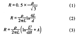
Where ρ--soil resistivity, Ω·m
d--equivalent diameter of steel, m
S--grounding grid area, m2
H--burial depth, m
L--length of grounding electrode, m
A--shape coefficient.
Equation (1) shows that in traditional grounding methods, when the soil resistivity is determined, to achieve the required resistance, sufficient grounding area is necessary. To reduce grounding resistance, the only way is to expand the grounding area. Every time the grounding area is expanded by 4 times, the grounding resistance is reduced by half. Equations (2) and (3) show that another method to reduce grounding resistance is to increase the size of grounding materials, but the material consumption is too large and the effect is not ideal. Therefore, better grounding materials and construction design methods are needed.
(2) Selection of grounding materials. Widely used grounding engineering materials include various metal materials, grounding electrodes, resistance-reducing agents, and ion grounding systems. Metal materials such as flat steel are commonly used, and copper materials are often used as substitutes, mainly for the construction of grounding loops, which are selected in most grounding projects. Grounding electrodes include metal grounding electrodes (angle steel, copper rods, and copper plates). These types of grounding electrodes have a short lifespan, rapid increase in grounding resistance, frequent grid renovation, and relatively high maintenance costs. Special structural grounding electrodes (with electrolyte materials) derived from traditional metal grounding electrodes have better performance and are generally called ion or hollow grounding systems. In addition, non-metallic grounding electrodes are convenient to use, have almost no lifespan constraints, and are widely recognized in various aspects.
(3) Application of grounding materials. Usually, the grounding resistance for lightning protection is 10Ω. In fact, inductive lightning protection for weak current equipment requires a grounding resistance of 4Ω or 1Ω. There is often a misconception that achieving a grounding resistance of 10Ω, 4Ω, or 1Ω meets the design requirements without considering the seasonal factor. Because soil resistivity changes with seasons, the grounding resistance required by the specification is actually the maximum allowable value. To meet this requirement, the grounding resistance of the grounding grid must reach: R=Rmax/ω
Where Rmax--maximum grounding resistance, which is the 10Ω, 4Ω, or 1Ω grounding resistance we mentioned
ω--seasonal factor, determined according to the region and engineering nature, with a common value of 1.45. Therefore, the grounding resistance we refer to is actually
R=6.9Ω (Rmax=10Ω), R=2.75Ω (Rmax=4Ω), R=0.65Ω (Rmax=1Ω)
In this way, the grounding grid meets the specification requirements and satisfies the design requirements even when the soil resistivity is highest (often in winter).
(4) Performance comparison of various grounding materials. Grounding materials are the main body of grounding work, and material selection is very important. Different grounding materials have their own advantages and limitations. In engineering practice, it is necessary to select grounding materials reasonably according to local conditions, achieving engineering design requirements at a lower cost. Several grounding materials (methods)
