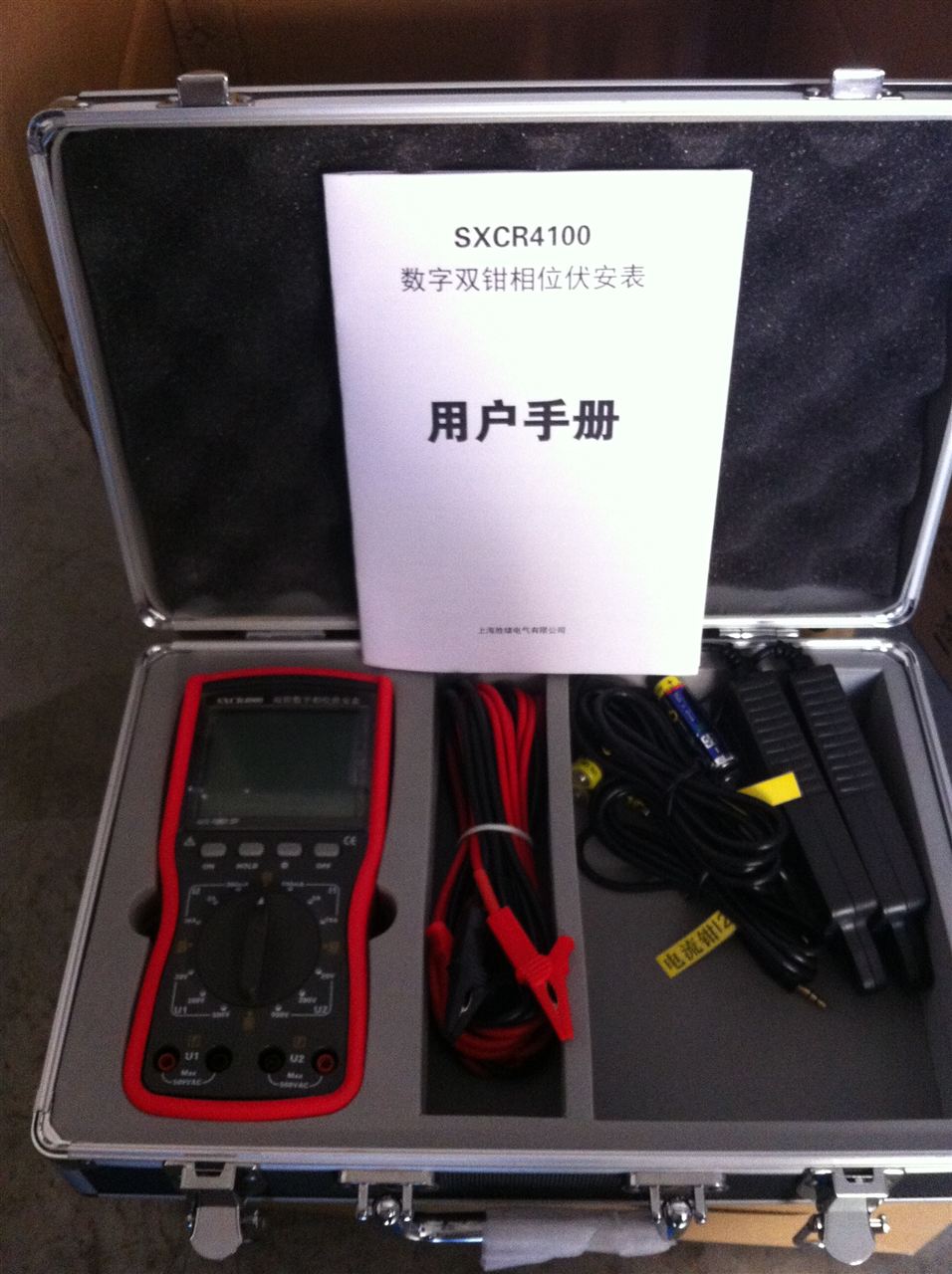
Instructions for using the dual-clamp phase voltmeter and operating instructions:
1. Instrument power supply
Lithium battery powered: When powered by battery, it can work for more than 18 hours with the backlight off, and more than 8 hours continuously with the backlight on. When the battery voltage is less than 3.5V, the instrument will not start; when the battery voltage is between 3.5V and 3.7V, the battery symbol is displayed in the upper right corner of the instrument and flashes continuously to indicate low battery, please charge as soon as possible. At this time, use the company's dedicated power adapter to connect the 220V mains power to the +5V charging port of the instrument, and press the number 0 key to charge the battery. At this time, the "*" in the upper right corner of the LCD screen flashes. When "*" is no longer displayed, the battery is fully charged.
This instrument has a power-saving management function. If no key is pressed within 2 minutes after power-on and no voltage or current signal is connected, the instrument will automatically shut down.
Backlight control: Press the number 8 key to turn the backlight on or off.
Note: The first three charges of the battery should preferably last more than 12 hours, and subsequent charges generally only need about 8 hours.
2. Digital dual-clamp phase voltmeter voltage, current, power, power factor, frequency measurement
Press the power key of the instrument, and the instrument first enters the voltage measurement interface. Voltage, current, power, power factor, frequency, and phase are the basic parameters for measurement and display. You can directly press the up and down arrow keys to view data at each level. The display screens are as follows:
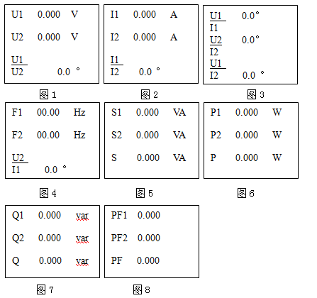
Phase parameter description: In Figure 1, UI/U2 represents the angle by which voltage U2 lags behind voltage U1
In Figure 2, I1/I2 represents the angle by which current I2 lags behind current I1
In Figure 3, U1/I1 represents the angle by which current I1 lags behind voltage U1
U2/I2 represents the angle by which current I2 lags behind voltage U2
U1/I2 represents the angle by which current I2 lags behind voltage U1
In Figure 4, U2/I1 represents the angle by which current I1 lags behind voltage U2
Other parameter descriptions: F---frequency S---apparent power
P---active power Q---reactive power
PF---power factor
When the measured voltage is less than 2V or the measured current is less than 4mA, the instrument will not perform measurement or display.
3. Data storage
On the measurement display interface, press the [F2] key, and the instrument displays the storage interface. The cursor flashes to prompt for meter number input. Press the number keys to input the meter number (up to 12 digits), press the [F4] key to delete the entered data, and press the confirm key to confirm. Note: The meter number must be entered when storing, otherwise data cannot be stored.
The instrument can save 60 sets of measurement data. Each set of stored data includes U, I, F, S, P, Q, PF, Φ group and total data, totaling twenty-four parameters.
4. Data query
On the measurement display interface, press the [F3] key, and the instrument display prompts for the meter number. Use the up, down, left, and right arrow keys to select the group number. After selecting the group number, press the [F3] key again to page through the data, and press [F1] to return to the measurement state.
5. Data deletion
On the query display interface, press the [F4] key, and the instrument displays number 1 and number 2. Number 1 deletes the current record, and number 2 deletes all records. After pressing the corresponding number key, the number flashes. Then press the confirm key to complete the deletion. Press the [F1] key to return to measurement
state.
6. Communication and data upload
On the measurement display interface, open the PC and enter the data management software interface. Connect the communication interface cable, press the [F4] key on the instrument, and the instrument enters the communication waiting state. On the PC data management interface, select to copy data. The recorded data stored in the instrument's internal memory can be transmitted to the computer through the interface, forming a user data file for long-term storage.
7. Time display and time setting
On the measurement display interface, press the number 9 key to enter the time display interface. The instrument displays year, month, day, current time, and day of the week. If you need to change it, press the number 9 again to enter the setting state. Move the cursor to the desired position and select the corresponding number to modify. Press the confirm key to complete time setting and return to the normal measurement interface.
8. Digital dual-clamp phase voltmeter data printing
In measurement mode, press the number 3 key to input the meter number and then enter on-site data printing. In query mode, press the number 3 key to directly print the currently queried data record. The LCD displays "P----" to indicate printing is in progress. After printing is completed, it returns to the corresponding mode before printing.
9. Data hold
On the measurement display interface, press the M key to lock the current measurement data. At this time, "*" is displayed in the upper right corner of the LCD screen. Press the M key again to unlock and resume normal measurement, and the "*" in the upper right corner of the LCD screen is no longer displayed.
10. Battery replacement
When the low battery indicator symbol appears on the LCD screen , it indicates that the battery is low and should be charged as soon as possible. If the battery is damaged and needs to be replaced, you must disconnect the input signal, turn off the power, open the battery compartment cover, pull out the battery outward, and reconnect the spare battery wires according to the color correspondence: red to red and black to black.
Maintenance and repair of the digital dual-clamp phase voltmeter:
Daily maintenance of the digital dual-clamp phase voltmeter
1. After each use of the instrument, please place the instrument and its accessories neatly and orderly in the portable aluminum alloy case according to the manufacturer's designed positions.
2. For the clamp-type current transformer, if it is not used for a long time, it is best to apply silicone grease at the opening and closing parts of the clamp head to prevent rust. If the operating environment is dusty, after using the meter, please wipe off surface dust with a damp cloth to keep the entire instrument clean and free of dirt.
3. If not used for a long time, please make sure the instrument is turned off to extend the battery life.
4. The DC battery of the instrument is powered by a high-efficiency lithium battery. To ensure effective battery use, please make sure to fully charge the battery for the first three charges.
Simple fault repair of the digital dual-clamp phase voltmeter:
1. The instrument cannot be turned on:
Cause: Low battery, battery problem, or instrument display problem
If the instrument is turned off and the power adapter is plugged in, the instrument will automatically turn on. If the instrument does not automatically turn on, it indicates a problem with the power adapter;
First check whether the battery has power. Plug the power adapter into the instrument's charging port and press the number 0 key to charge the battery. After fully charged, unplug the adapter and then turn on the instrument;
If the instrument shows the battery is fully charged but still cannot be turned on, the battery is faulty and needs to be replaced with a spare battery;
If it still cannot be turned on after replacing the spare battery, the instrument main unit is faulty and must be returned to the factory for repair.
2. Current is not measured:
Cause: Poor contact of the current clamp, poor contact of the current channel, or a fault in the current measurement circuit
The standard configuration of this instrument has a maximum current range of 10A. Please check whether the load current is within the allowable measurement range. If it exceeds the measurement range, the instrument will not display;
First check whether the wiring is good and whether there are foreign objects on the silicon steel sheets of the current clamp. After inspection and cleaning, reconnect the current clamp and current jack tightly. If there is still no current value, you can connect another current clamp with a signal to that jack. If there is a measurement value, it indicates that the original current clamp has poor contact and the wire or current clamp needs to be replaced;
If other current clamps also show no measurement value in that current channel, it indicates a problem with the instrument's main unit current jack or current measurement circuit, and the instrument must be returned to the factory for repair.
3. Voltage is not measured:
Cause: The load voltage signal is too low or the voltage wire has poor contact
The standard configuration of the digital dual-clamp phase voltmeter has a voltage range of 5-500V. Please check whether the voltage signal is within the allowable measurement range. If it exceeds the measurement range, the instrument will not display;
Check whether the voltage wire is broken. You can connect another voltage test wire to the voltage channel for measurement. If it measures normally, it can be determined that the voltage wire has poor contact or is broken, and the voltage test wire needs to be replaced;
If no voltage signal is detected after connecting other voltage test wires, there is a problem with the voltage measurement channel. Please contact the manufacturer for return and repair.
Related technical products please refer to: DigitalDual-Clamp Phase Voltmeter