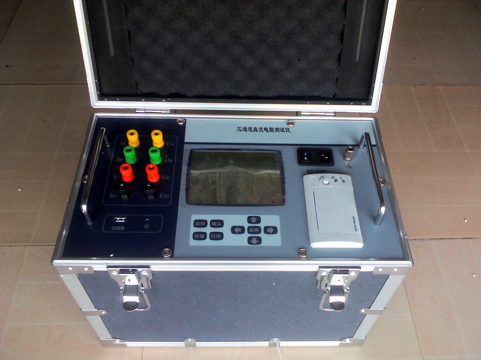
Based on the actual testing of small and medium-sized transformers, this paper introduces the measurement methods, precautions, and specification requirements for DC resistance of transformer coils, and specifically analyzes the measurement results of common faults such as coil breakage and inter-turn short circuits.1 DC Resistance Measurement
1.1 Measurement Methods
Measuring DC resistance is an important item in transformer testing. Through measurement, defects such as poor contact in the conductive circuit, poor soldering, coil faults, and wiring errors can be detected. In the actual measurement of small and medium-sized transformers, the DC bridge method is mostly used. When the resistance value of the tested coil is above 1 ohm, a single-arm bridge is used; below 1 ohm, a double-arm bridge is used. When wiring with a double-arm bridge, the potential terminals of the bridge should be close to the measured resistance, and the current terminals should be connected above the potential terminals. Before measurement, estimate the resistance value of the coil under test, set the bridge multiplier knob to an appropriate position, short-circuit and ground the non-tested coils, then turn on the power switch to charge. After sufficient charging, press the galvanometer switch and quickly adjust the measuring arm to move the galvanometer pointer toward the zero line in the middle of the galvanometer scale, fine-tune until the pointer stops steadily at zero, then record the resistance value. At this time, the resistance of the tested coil = multiplier × measuring arm resistance. After measurement, first release the galvanometer button, then turn off the power switch.
1.2 Precautions
During the measurement process, in addition to strictly complying with electrical safety regulations and equipment testing procedures, special attention should be paid to:
1) Measure when the coil temperature is stable, requiring that the temperature difference between the upper and lower parts of the transformer tank does not exceed 3°C;
2) Since the transformer coil has inductance, the charging current during measurement is not very stable. Be sure to count only after the current is stable, and if necessary, take measures to shorten the charging time;
3) Minimize the contact resistance of wires in the test circuit. The taps of an operating transformer are often affected by oil film and other contaminants, causing poor contact. Generally, switch several times before measuring to avoid misjudgment.
2 Analysis of Measurement Results
2.1Specification Requirements
According to specification requirements, for three-phase transformers, the line-to-line resistance should be measured; for transformers with a neutral point lead, the phase resistance should be measured; for coils with taps, during major overhauls and acceptance tests, the coil resistance at all tap positions should be measured, while during minor overhauls and preventive tests, only the resistance at the tap position in use needs to be measured. Due to differences in transformer manufacturing quality, maintenance level of the operating unit, accuracy of the instruments used by test personnel, and measurement wiring methods, the measured three-phase resistance values may differ. The following error formula is usually introduced for judgment:
△R% = [(Rmax - Rmin)/RP] × 100%
RP = (Rab +Rbc +Rac ) / 3
Where △R% –––– percentage error
Rmax –––– maximum value in actual measurement (Ω)
Rmin –––– minimum value in actual measurement (Ω)
RP –––– average value of the three-phase actual measurements (Ω)
Specification requirements: For transformers above 1600 kVA, the difference among the DC resistance values of each phase coil should not exceed 2% of the three-phase average; for transformers below 1600 kVA, the difference among the DC resistance values of each phase coil should not exceed 4% of the three-phase average, and the line-to-line difference should not exceed 2% of the three-phase average; compared with the previous measurement, the change should not exceed 2% of the previous measured value.
2.2 Relevant Conversions
When performing comparative analysis, it must be done at the same temperature. If the temperature is different, convert to the resistance value at 20°C using the following formula:
R20°C = RtK, K = (T + 20) / (T + t)
Where R20°C –––– DC resistance value at 20°C (Ω)
Rt –––– DC resistance value at t°C (Ω)
T –––– constant (234.5 for copper conductors, 225 for aluminum conductors)
t –––– temperature during measurement
To determine the phase where the defect is located, for three-phase transformers without a neutral point lead, it is necessary to convert the measured line-to-line resistance into per-phase resistance. Let the measurable line-to-line resistances of the three-phase transformer be Rab, Rbc, Rac, and the per-phase resistances be Ra, Rb, Rc. When the transformer coil is connected in Y configuration, the phase resistances are:
Ra = (Rab + Rac - Rbc) / 2
Rb = (Rab + Rbc - Rac) / 2
Rc = (Rac + Rbc - Rab) / 2, if the three phases are balanced, the phase resistance is equal to 0.5 times the line resistance. When the transformer coil is connected in Δ configuration, with a connected to y, b to z, and c to x, then:
Ra = (Rac - RP) - RabRbc / (Rac - RP)
Rb = (Rab - RP) - RacRbc / (Rab - RP)
Rc = (Rbc - RP) - RabRac / (Rbc - RP)
When the transformer coil is connected in Δ configuration, with a connected to z, b to x, and c to y, then:
Ra = (Rab - RP) - RacRbc / (Rab - RP)
Rb = (Rbc - RP) - RabRac / (Rbc - RP)
Rc = (Rac - RP) - RabRbc / (Rac - RP)
Where RP = (Rab + Rbc + Rca) / 2, if the three phases are balanced, the phase resistance is equal to 1.5 times the line resistance.
3 Case Analysis
From the actual measurement results, it can be seen that there are many factors causing the transformer coil resistance value to exceed the specification requirements. In terms of measurement technology, the main factors include insufficient bridge accuracy, incorrect measurement wiring, excessive lead resistance and wiring contact resistance, short charging time of the transformer, insufficient bridge voltage, etc. In terms of the transformer itself, the main factors include poor contact of taps, poor soldering of coils or leads, breakage, poor contact between bushing conductor rod and lead, and short circuits between turns, layers, or phases of the coil. For delta-connected transformers, if the resistance values already reflect that the defect is only in one phase, the simplified formula can be used to obtain the phase resistance for analysis, i.e., when Rab = Rbc ≠ Rac, then Rb = Rc ≠ Ra. The measurement results of several common fault phenomena are analyzed as follows:
|
Fault Phenomenon (compared with normal test values) |
Analysis Result |
|
|
Y Connection |
Δ Connection |
|
|
One line-to-line resistance value unchanged, two line-to-line resistance values cannot be measured (very large resistance) |
Two line-to-line resistances increase by 1.5 times the normal value, one line-to-line resistance is 3 times the normal value |
One phase coil broken |
|
One line-to-line resistance value unchanged, two line-to-line resistance values drop to (0.5~1) times the normal value |
Two line-to-line resistance values increase to (1~3) times the normal value, one line-to-line resistance value drops to (0~1) times the normal value |
One phase coil inter-turn short circuit |
|
One line-to-line resistance value unchanged, two line-to-line resistance values increase |
One line-to-line resistance value unchanged, two line-to-line resistance values increase |
Poor contact between one phase lead and conductor rod |
|
Three line-to-line resistance values cannot be measured (very large resistance) |
One line-to-line resistance equals 3 times the normal value, two line-to-line resistance values cannot be measured (very large resistance) |
Two phase coils broken |
|
All three line-to-line resistances drop to (0.5~1) times the normal value, with one of them much lower |
All three line-to-line resistance values drop to (0~1) times the normal value, with two of them much lower |
Two phase coils inter-turn short circuit |
|
All three line-to-line resistance values increase compared to normal, with one of them increasing much more |
All three line-to-line resistance values increase compared to normal, with one of them increasing much more |
Poor contact between two phase leads and conductor rods |