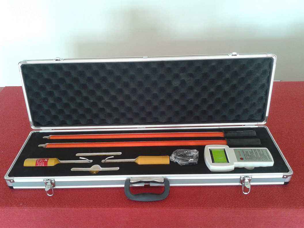
The high-voltage wireless phase verifier consists of two components that are electrically isolated from each other. The device is equipped with electrodes that can be connected to the tested conductor. One is an orange transmitter with hook-shaped electrodes for hanging onto the wire, and the other is a yellow receiver with Y-shaped electrodes for easy contact with the conductor. These electrodes serve as antennas for transmitting and receiving signals. The ends of both the transmitter and receiver should be connected to insulated operating rods. The design of the high-voltage wireless phase verifier can achieve verification of the grid structure, and for three-phase connected lines, it can confirm the relative phase of different conductors. There is no electrical connection between the two measuring components, making the application of the measuring device very flexible and safe.
Working Principle of High-Voltage Wireless Phase Verifier
1. The transmitter detects whether the tested conductor has voltage. It can act as a voltage detector, emitting intermittent audible and visual indications for live conductors. Once the voltage detection is completed (after 5-10 seconds), the transmitter automatically switches to phase measurement. The transmitter continuously sends a radio frequency signal with phase characteristics to the receiver. In this case, the line also serves as an antenna, and continuous light indication shows that the transmitter is working normally in this sequence.
2. The receiver has only one purpose, which is phase measurement, while the transmitter is also working. In order to:
a. Receive the radio frequency signal from the transmitter;
b. Compare the measured phase with the received phase characteristic signal in real time;
c. Ensure that there is voltage on the conductor;
d. When in phase, the receiver will emit a continuous strong light and sound signal; when out of phase, the receiver emits a weak light signal, which only indicates that the conductor contacted by the receiver has voltage.
The high-voltage wireless phase verifier is applied to phase verification and phase sequence verification of power lines and substations. It has reliable high-voltage electrical safety isolation performance, complies with power industry standards, has strong anti-interference capability, and meets electromagnetic compatibility (EMC) standards. This product is safe, reliable, stable in performance, and easy to operate, making it an ideal phase verification instrument.
System Functional Characteristics of High-Voltage Wireless Phase Verifier
The high-voltage wireless phase verifier system uses all digital circuits, with complete functions and low power consumption. Under normal use, the battery only needs to be replaced once a year (due to natural discharge of ordinary batteries). The test system consists of: host (receiver), X collector (transmitter), Y collector (transmitter), needle-type and hook-type collection heads, and retractable insulated operating rods. (Accessories include aluminum alloy carrying case, spare batteries, and special calibration test clips with plugs).
1) The X and Y collectors are easy to use, and the host has an auto power-off function. The insulated rod adopts a retractable telescopic rod. No wiring is needed during on-site phase verification, and the phase verification distance can reach 70 meters, unaffected by various on-site conditions. The entire phase verification process can be completed by two people within 2 minutes.
2) Phase verification can be performed between two different voltage levels, allowing both qualitative measurement (in phase, out of phase) and quantitative measurement (phase angle difference between two power supply lines, such as 30°, 60°, etc.).
3) The X and Y collectors send the collected voltage phase signals to the host via wireless signals, with reliable high-voltage electrical safety isolation performance. This product uses all digital circuits, with strong anti-interference capability and stable and accurate data.
4) Voltage detection function: When the collection head of the X or Y collector contacts the live part of a high-voltage line or electrical equipment, if the line or equipment is energized, the host will display X or Y.