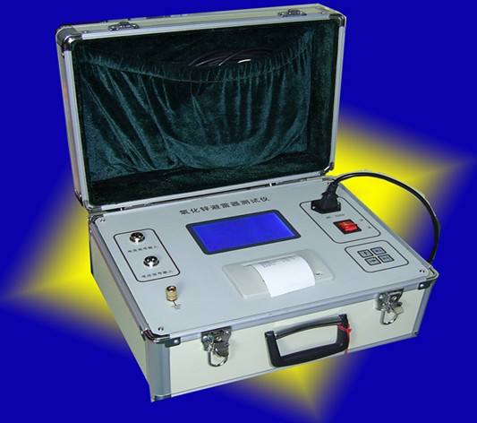
The zinc oxide arrester live tester is a specialized instrument used to detect the electrical performance of zinc oxide arresters. This instrument is suitable for live or offline testing of zinc oxide arresters at various voltage levels, thereby promptly identifying dangerous defects such as internal insulation moisture and valve plate aging. The instrument is simple to operate and convenient to use. The entire measurement process is controlled by a microcontroller. It can measure the total current, resistive current and its harmonics, power frequency reference voltage and its harmonics, active power, and phase difference of zinc oxide arresters. The large screen can display the real waveforms of voltage and current. The instrument employs digital waveform analysis technology and uses software anti-interference methods such as harmonic analysis and digital filtering to ensure accurate and stable measurement results.
1. Zero adjustment of the instrument meter
After using the zinc oxide arrester tester for a period of time, it may need adjustment. Remove the instrument core from the case, start the instrument, and the alarm light will turn on (do not connect the test sample at this time). Press and hold the test button, and adjust the corresponding potentiometer on the indicator meter until the meter readings are "zero ±1 digit" for voltage and current zero adjustment respectively.
2. Calibration of 0.75U1mA
Set the calibration button to the 0.75U1mA state, connect the test sample, press the test button, read the voltage value of U1mA, then release the test button. At this time, the instrument voltage will immediately change to another voltage value U1, which is 0.75U1mA. Compare the two. If U1 = 0.75U1mA, no adjustment is needed; if U1 ≠ 0.75U1mA, make appropriate adjustments by adjusting the corresponding potentiometer on the circuit board until U1 = 0.75U1mA. After calibration, the instrument can ensure measurement accuracy for a considerable period without frequent adjustment. After calibration, set the calibration button back to the U1mA state.
3. Instrument error adjustment
After using the instrument for a period of time, if errors are found, adjustments can be made. After connecting the test sample, if the U1mA value is determined, for example, 27.0kV, press and hold the test button and check whether the voltage meter reading equals the reference voltage U1mA (27.0kV) of the tester. If not, adjust the reference potentiometer on the left side of the voltage meter head. After adjustment, release the test button. (See Figure 1 below for the reference voltage adjustment.)
4. Simple fault handling
If the ammeter display shows "[[[" or returns to zero, it indicates that the input protection operational amplifier (CA3140E) IC1 in the current loop is damaged, equivalent to a blown fuse. Replace the configured component.