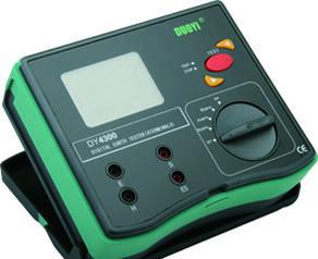
1. Working Principle
This instrument abandons the traditional manual hand-cranked power generation method, adopts advanced medium and large-scale integrated circuits, and applies DC/AC conversion technology to combine three-terminal and four-terminal measurement methods into a new type of ground resistance tester with a single model.
The working principle is that the internal DC/AC converter converts DC into low-frequency constant current, which forms a loop through the auxiliary grounding electrode C and the tested object E. An AC voltage drop is generated on the tested object, which is sent to the AC amplifier through the auxiliary grounding electrode P for amplification, and then after detection, it is displayed on the meter. With the help of the multiplier switch, three different ranges can be obtained: 0~2Ω, 0~20Ω, 0~200Ω.
2. Application Scope
This instrument is suitable for measuring the ground resistance of various devices in electric power, posts and telecommunications, railways, communications, mining and other departments, as well as measuring the resistance value of low-resistance conductors; it can also measure soil resistivity and ground voltage.
3. Main Features
• The structure uses high-strength aluminum alloy as the casing, and in the circuit, to prevent power frequency and radio frequency interference, a phase-locked loop synchronous tracking detection method is adopted, combined with a switched capacitor filter, giving the instrument good anti-interference capability.
• DC/AC conversion technology is used to convert DC into low-frequency constant current for easy measurement.
• The auxiliary grounding resistance is allowed to vary between 0~2KΩ (RC) and 0~40KΩ (RP) without affecting the measurement results.
•This instrument does not require manual balance adjustment, has a 3(1/2)-digit LCD display, and besides measuring ground resistance, it can also measure low-resistance conductor resistance, soil resistivity, and AC ground voltage.
•If the test loop is open, the meter displays "1" indicating overflow, which conforms to conventional measurement habits.