1.2.1. Preparation before testing
For the convenience of discussion, assume that the setting values of a certain protection are: overcurrent: 5A; undervoltage blocking value: 60V; negative sequence voltage: 6V.
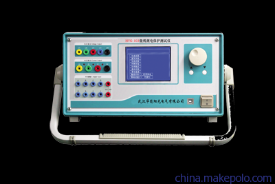
1. Correct wiring: The three-phase voltages UA, UB, and UC of the tester should be connected to the three-phase voltage input terminals of the protection respectively; the IA of the tester should be connected to the current input terminal of a certain phase of the protection, for example, phase A; the binary input terminal TA and common terminal TN of the tester should be connected to the two ends of the protection trip contact respectively. When the protection has an active contact, it should also be ensured that the common terminal TN of the tester is connected to the positive power terminal of the protection. It is worth noting that for some protections, the negative sequence voltage and undervoltage are connected through different voltage terminals. Therefore, when performing the following "check blocking voltage value" and "check negative sequence voltage value" tests, wiring should be done separately.
2. Please check that in the setting values of the protection, the composite voltage blocking overcurrent function should be enabled. If the test is to make the protection's stage II overcurrent protection operate, at least the composite voltage blocking overcurrent function of stage II overcurrent should be enabled.
1.2.2. Check blocking condition
The tester outputs a line voltage of 70V (single-phase voltage is 40.4V, and the phases of three-phase voltages UA, UB, UC are 0°, 240°, and 120° respectively), which is greater than the blocking voltage of 60V, so the protection is in a blocking state. The tester outputs phase current with an initial value of 3A and a step of 0.1A, gradually increasing the phase current to 7A, and it should be verified that the protection does not operate.
1.2.3. Check overcurrent setting value
The tester outputs a line voltage of 50V (single-phase voltage is 28.8V, and the phases of three-phase voltages UA, UB, UC are 0°, 240°, and 120° respectively), which is less than the blocking voltage of 60V, so the blocking is released and operation is allowed. The tester outputs phase current with an initial value of 3A and a step of 0.1A, gradually increasing the phase current until the protection operates. The operating current of the protection is measured and compared with the set overcurrent value.
1.2.4. Check blocking voltage value
Set the initial voltage output by the tester to 70V, which is greater than the blocking voltage; the initial current is 7A, which is greater than the overcurrent setting value, and set the voltage as a variable with a step of 0.1V for all three-phase voltages. After starting the test, the protection is in a blocking state. Gradually reduce the line voltage until the protection operates, measure the operating voltage, and compare the line voltage output by the tester at that time with the undervoltage blocking setting value of the protection.
Note: Since there is a certain delay for the protection to transition from the blocking state to the unblocked state, to ensure the accuracy of the test, when manually reducing the voltage, before approaching the protection operation, sufficient time should be allowed to wait for the protection to operate after each step reduction.
1.2.5. Check negative sequence voltage value
Since the set negative sequence voltage value is smaller than the undervoltage blocking value, to prevent interference, before the test, first set the undervoltage blocking value of the protection to 3V, which is less than the negative sequence voltage.
Set the initial negative sequence line voltage output by the tester to 4V (single-phase voltage is 2.3V, and change the phases of the three-phase voltages to 0°, 120°, and 240° respectively), which is less than the set negative sequence voltage; the initial current is 7A, which is greater than the overcurrent setting value, and set the voltage as a variable with a step of 0.1V (the steps of voltages UA, UB, UC should be the same). After starting the test, the protection does not operate. Gradually increase the line voltage until the protection operates, measure the operating voltage, and compare it with the negative sequence voltage setting value of the protection.