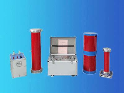
The working principle wiring of the variable frequency series resonance withstand voltage test device is shown in the figure. The AC 220V power frequency power supply outputs a voltage with adjustable frequency of 30~200Hz through the variable frequency control unit, which is sent to the excitation transformer, boosted to 0~1000V, and then through the resonant reactor L and the test object CX, forming a high-voltage main resonant circuit. The capacitive voltage divider is purely capacitive and is used to measure the test voltage. First, the variable frequency control unit sends a lower voltage Ue to the main resonant circuit through the excitation transformer, and adjusts the output frequency of the variable frequency control unit. When the frequency meets the condition ΩL=1/ΩC,
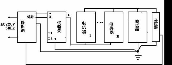
the circuit reaches the resonance state. At this time, under a smaller excitation voltage Ue, a voltage UCX several tens of times Ue can be generated on the test object CX. The variable frequency test system works on the principle of series resonant circuit. The resonance point is achieved by adjusting the frequency of the frequency converter to the natural frequency of the series resonant circuit. After the circuit resonates, the output voltage waveform is a pure sine wave, and the frequency of the system depends on the L-C parameters of the circuit. Among them, the reactance value of the reactor is adjustable, and the frequency of the system depends on the size of the load capacitance, as shown in the above formula. According to the size of CX, the inductance L of the reactor can be appropriately adjusted so that the resonant frequency is fixed within a required range, thereby meeting the test of test objects that must undergo AC withstand voltage test under power frequency conditions.
From the above working principle, it can be seen:
1. The higher the quality factor, the smaller the required power supply capacity.
2. The resonant reactor L and the test object CX are in a resonant state, and this circuit forms a good filter circuit, so the output voltage UCX is a good sine waveform.
3. When the test cable breaks down, the resonance condition is lost, and the current in the high-voltage circuit and the low-voltage power supply circuit decreases instead, so the arc at the insulation breakdown point will not expand the fault point, making it convenient for maintenance.
Precautions for the variable frequency series resonance withstand voltage test device:
1. This test equipment should be used by professional high-voltage test personnel. Before use, carefully read the instruction manual and undergo repeated operation training.
2. There should be no less than 2 operators. During use, strictly abide by the safety operation regulations for high-voltage tests of the unit.
3. To ensure the safety and correctness of the test, in addition to being familiar with this product manual, it is necessary to strictly follow the national
relevant standards and regulations for test operation.
4. All connecting wires must not be connected incorrectly, especially the grounding wire. Otherwise, it may cause damage to the test device.
5. When this device is in use, it outputs high voltage or ultra-high voltage. It must be reliably grounded, and pay attention to operational safety.
6. If the voltage cannot be increased after power-on and returning to zero, press and hold the reset button for a long time (about 10 seconds), and make sure the indicator lights on the control box panel are normal, that is, no other red lights are on except "high voltage", then start normal operation.
7. When the voltage is greater than 10V and tuning has not been performed, the system will automatically detune to prevent high voltage from being generated upon resonance, which could damage the test object or even cause harm to the human body.