The longitudinal insulation of a transformer mainly relies on the insulating media within the windings - the insulating varnish of the enameled wire itself, transformer oil, insulating paper, impregnating varnish, insulating adhesive, etc. (Different types of transformers may contain one or more of these insulating media). It is difficult to ensure 100% purity of the longitudinal insulation dielectric, which inevitably contains solid impurities, bubbles, or moisture, and may also suffer varying degrees of damage during the production process. The highest field strength during transformer operation is concentrated at these defects. The temperature rise from long-term load operation reduces the breakdown voltage of the insulating medium, causing partial discharge. The power absorbed by the dielectric through the applied alternating electric field, i.e., dielectric loss, significantly increases, leading to severe heating of the dielectric, increased dielectric conductance, and the large current in that area also generates heat, causing the dielectric temperature to continue rising, which in turn increases the conductance of the dielectric. This vicious cycle over time eventually leads to thermal breakdown of the dielectric and destruction of the entire transformer. This fault manifests in the transformer's characteristics as a significant increase in no-load current and no-load power consumption, along with undesirable phenomena such as burning heat, arcing, vibration, and whistling in the windings. It is thus extremely necessary to use the induced voltage withstand test to detect whether a transformer contains longitudinal insulation defects.
Compared to the main insulation of a transformer, i.e., the insulation between windings and between windings and the core, transformers also have another important insulation performance indicator - longitudinal insulation. Longitudinal insulation refers to the insulation between different points and different parts of the transformer windings at different potentials, mainly including the insulation performance between turns, layers, and sections of the windings. The "induced voltage withstand test" specified in national standards and IEC (International Electrotechnical Commission) standards is one of the test methods specifically used to verify the longitudinal insulation performance of transformers.
Principle of Induced Voltage Withstand Test
When a transformer is newly produced, it has not been subjected to long-term harsh environmental conditions. Applying a power supply at its rated voltage and frequency for testing, the voltage between turns, layers, and sections of the windings is insufficient to reach the breakdown voltage at dielectric defects, making it difficult to cause discharge and breakdown at these insulation defects. Such transformers with potential insulation faults show little difference in no-load current and no-load power consumption compared to similar transformers with good insulation performance, making it difficult to detect these hidden dangers.
The induced voltage withstand test applies a voltage more than twice the rated voltage to the transformer, which can establish a higher and more concentrated field strength at longitudinal insulation defects, causing the voltage between turns, layers, and sections to reach and exceed the breakdown voltage at dielectric defects. The induced voltage withstand test applies a frequency more than twice the rated frequency; the higher frequency can significantly reduce the breakdown voltage of solid dielectrics, making insulation defects easier to break down. The specified duration of the applied voltage in the induced voltage withstand test also ensures the breakdown of insulation defects. Therefore, the induced voltage withstand test can reliably detect the quality of the transformer's longitudinal insulation.
The reason why the induced voltage withstand test applies a power frequency more than twice the rated frequency is that the magnetizing current i of the transformer - the characteristic curve of the main flux amplitude Фm is generally designed to be close to the bending saturation part at rated frequency and rated voltage (as shown in Figure 1). Moreover, when the power frequency is constant, the main flux Фm is determined by the applied voltage U:
U=E=4.44WfФm Фm
U – applied power supply voltage, V △Фm
E – induced electromotive force of the energized winding, V
f – applied power supply frequency, Hz
W – number of turns of the energized winding, n
Therefore, applying a voltage more than twice the rated voltage to the transformer △i i
will inevitably cause severe saturation of the iron core, increasing the main flux Фm by △Фm, and the magnetizing current i will increase sharply, causing the transformer to heat up and burn out. To keep the iron core from saturating when applying more than twice the voltage, it is necessary to increase the power frequency to more than twice the rated frequency.
The induced voltage withstand test applies a power supply with more than twice the voltage and more than twice the frequency to the primary side of the transformer. The main flux will induce induced electromotive forces E1 and E2 in both the primary and secondary sides, each being more than twice their rated operating values. Therefore, the induced voltage withstand test can simultaneously test the longitudinal insulation performance of both the primary and secondary windings. Of course, we can also completely perform the test from the secondary side of the transformer as needed, but the applied voltage should be more than twice the no-load voltage under rated operating conditions, and the frequency should also be more than twice the rated frequency.
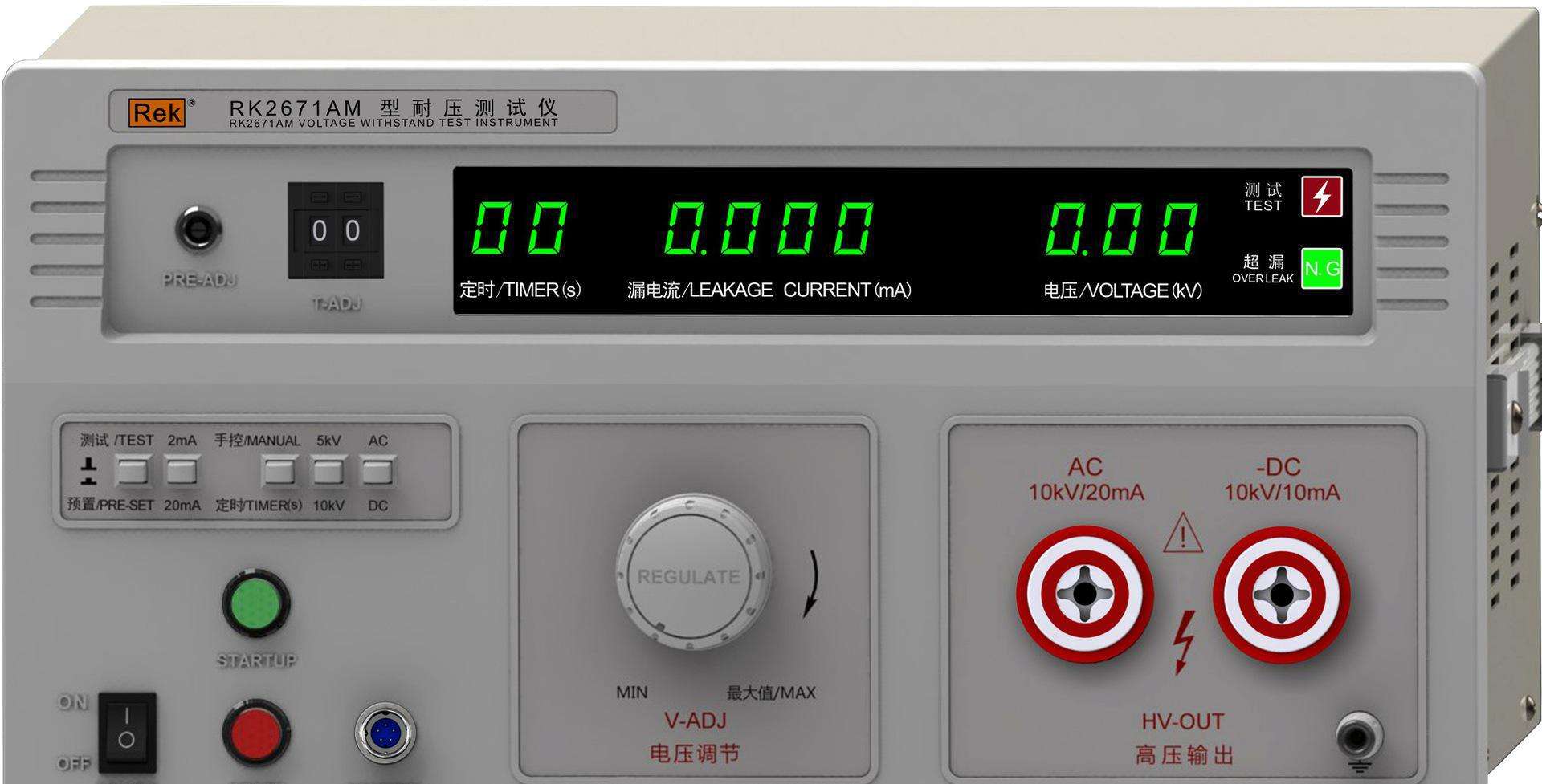
Hope this article can help you! Welcome to purchase our company's Insulation Withstand Voltage Tester!!
Wireless Phase Checker Test Transformer Wireless Phase Checker Wireless Phase Checker Test Transformer Test TransformerWireless Phase Checker Wireless Phase Checker Wireless Phase Checker Test Transformer Test Transformer Test Transformer Test Transformer Test Transformer Test Transformer DC High Voltage Generator Current Booster